\documentclass[border=3pt]{standalone}

% Circuits
\usepackage[european, straightvoltages, RPvoltages, americanresistor, americaninductors]{circuitikz}
\tikzset{every picture/.style={line width=0.2mm}}

% Notation
\usepackage{amsmath}

% Tikz Library
\usetikzlibrary{calc}

% Bipoles Specifications
\ctikzset{bipoles/thickness=1.2}

\begin{document}

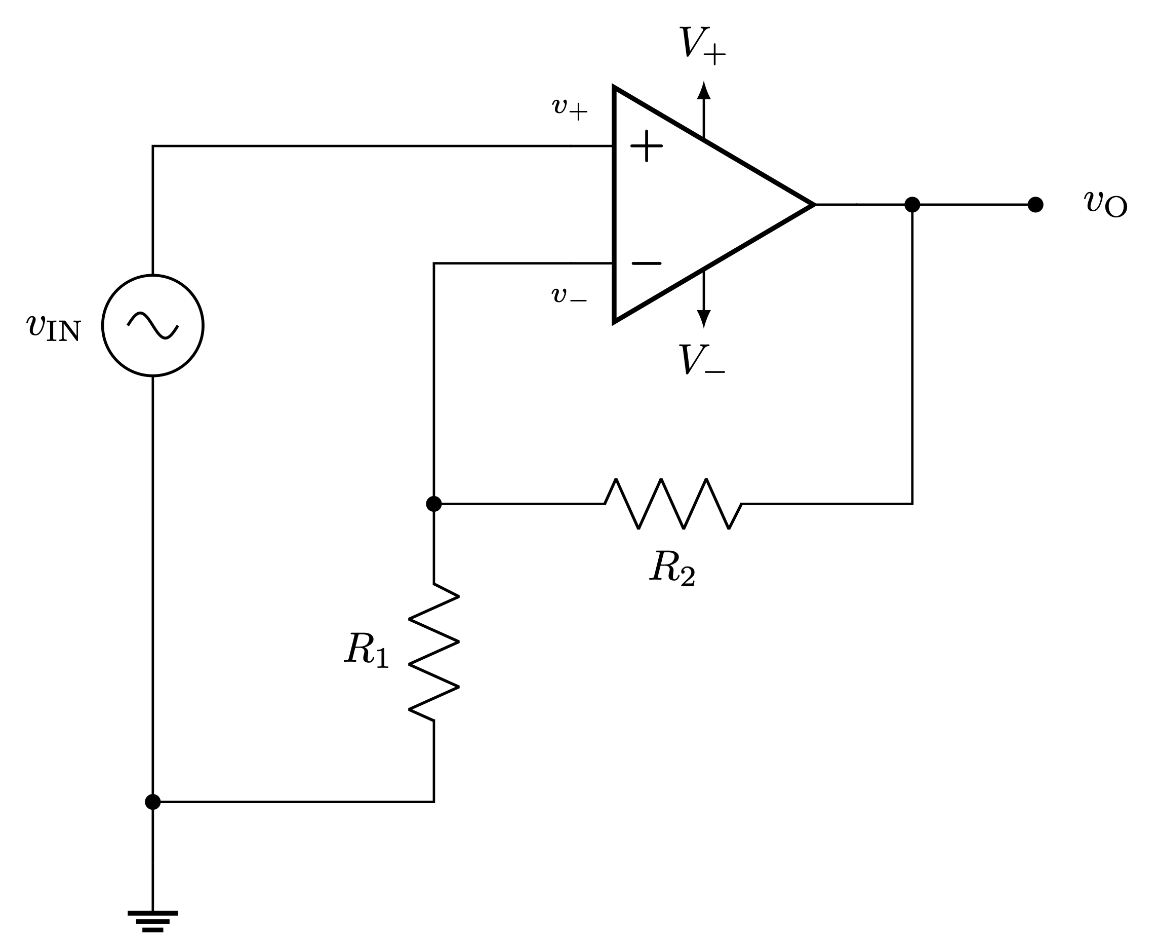
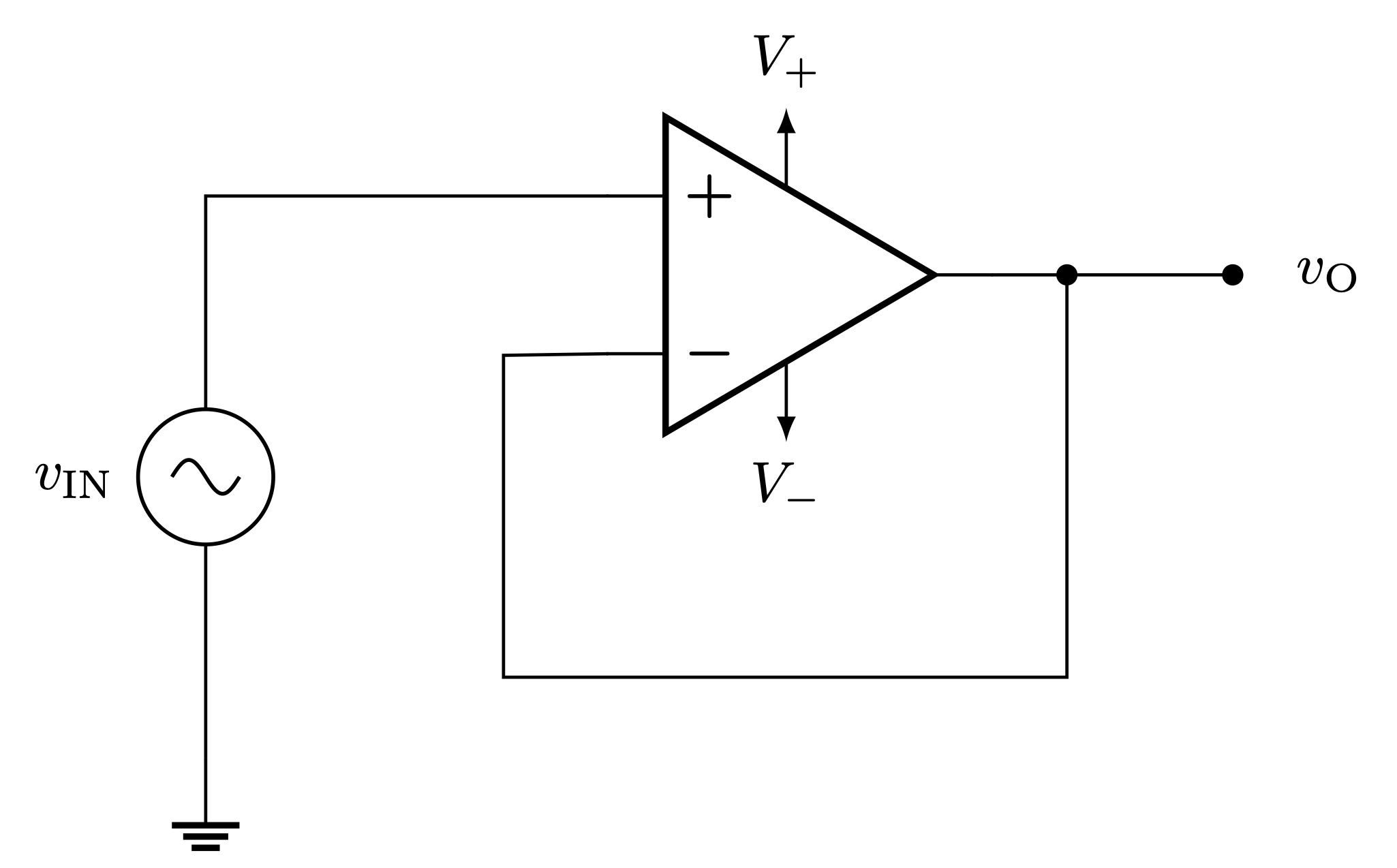
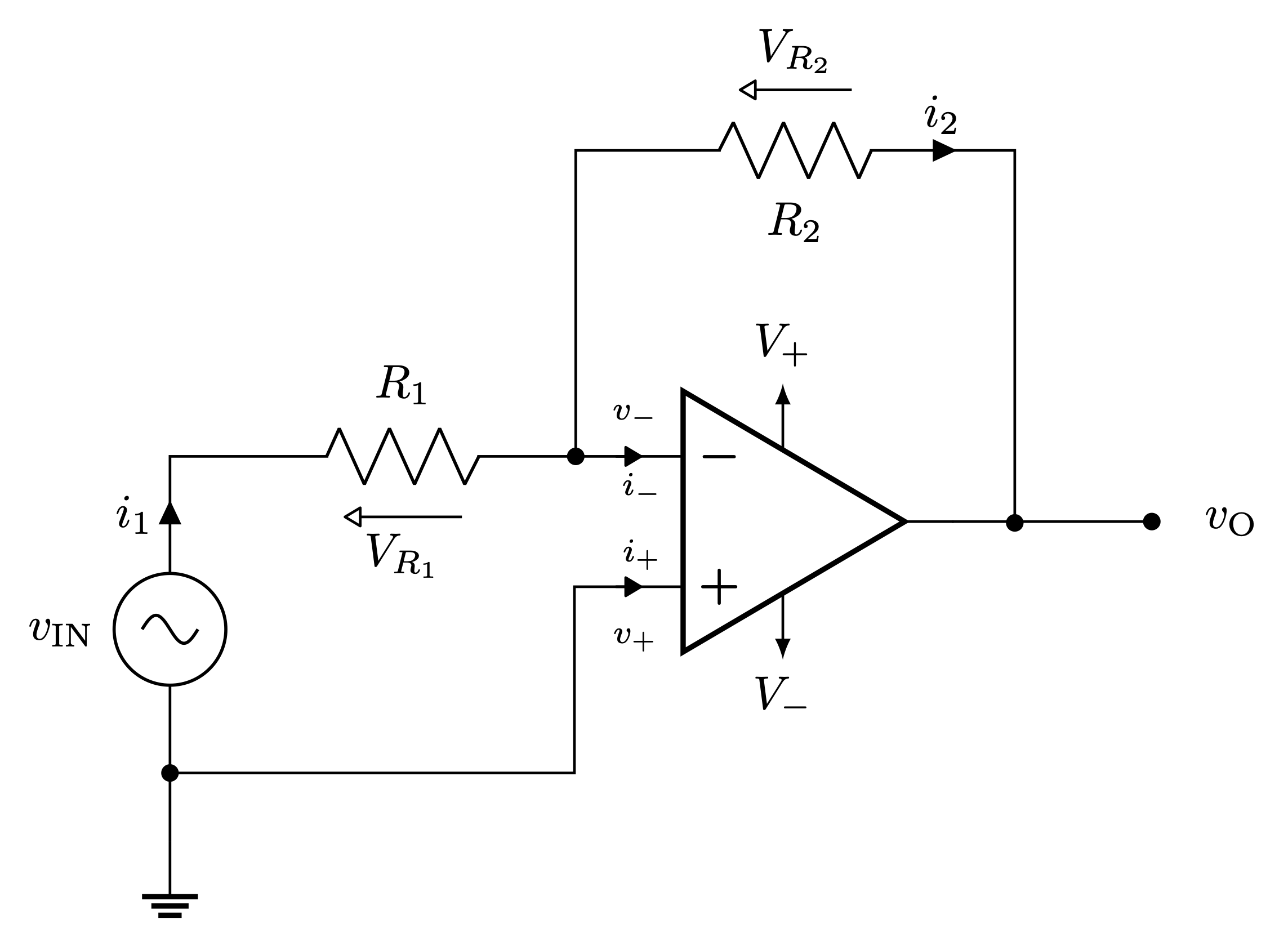
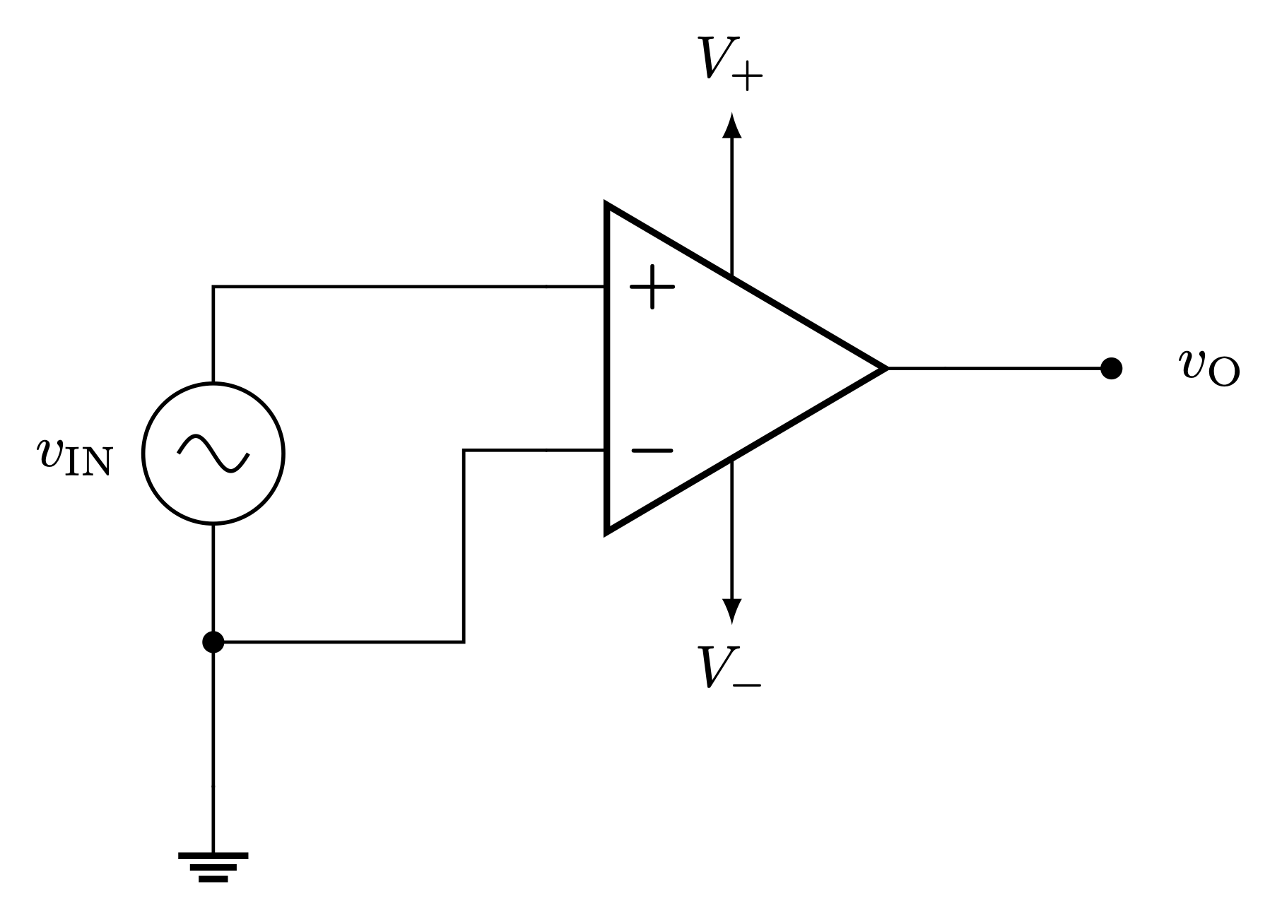
\begin{circuitikz}
		%Circuit
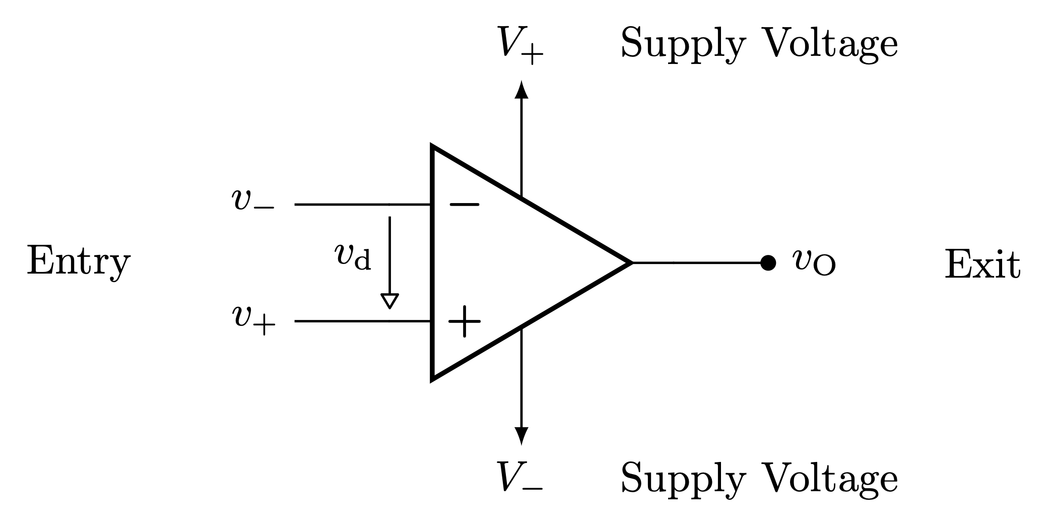
		\draw (0,0) node[op amp] (opamp) {};
		\draw (opamp.+) -- +(-0.8,0) node[left] {$v_+$};
		\draw (opamp.-) -- +(-0.8,0) node[left] {$v_-$};
		\draw (opamp.out) to[short,-*] +(0.8,0) node[shift={(0.4,0)}] {$v_\text{O}$};
		\draw[-latex] (opamp.up) -- +(0,1) node[above] (vv) {$V_+$};
		\draw[-latex] (opamp.down) -- +(0,-1) node[below] (v) {$V_-$};
		%
		\draw[-{Triangle[round,open]}] ($(opamp.-)+(0,-0.1)$) -- ($(opamp.+)+(0,0.1)$) node[pos=0.44, left] {$v_\text{d}$};

		%Nodes
		\node[shift={(-3.8,0)}] ($opamp.+!0.5!opamp.-$) {Entry};
		\node[shift={(+3.8,0)}] (opamp.out) {Exit};
		\node[shift={(+2,0)}] at (vv) {Supply Voltage};
		\node[shift={(+2,0)}] at (v) {Supply Voltage};

\end{circuitikz}

\end{document}


