")


Inspiration from Wikipedia.

Edit and compile if you like:
% Author: Izaak Neutelings (March 2019)
% Inspiration: https://commons.wikimedia.org/wiki/File:Stirling_Animation.gif
\documentclass[border=3pt,tikz]{standalone}
\usetikzlibrary{calc}
\tikzset{>=latex} % for LaTeX arrow head
\colorlet{mylightblue}{blue!10}
\colorlet{mydarkblue}{blue!30!black}
\tikzstyle{arrow}=[->,line width=2,mydarkblue]
\tikzstyle{vector}=[->,line width=3,green!50!black]
\tikzstyle{gas}=[top color=blue!20,bottom color=red!30]
\tikzstyle{knob}=[line width=2,mydarkblue,fill=blue!20!black!80]
\tikzstyle{wall}=[line width=2,mydarkblue,top color=blue!10!black!50,bottom color=blue!10!black!40]
\tikzstyle{arm1}=[very thick,mydarkblue,top color=blue!20!black!25,bottom color=blue!20!black!50]
\tikzstyle{arm2}=[very thick,mydarkblue,top color=blue!20!black!50,bottom color=blue!20!black!60]
\tikzstyle{piston1}=[very thick,mydarkblue,top color=blue!20!black!60,bottom color=blue!20!black!70,middle color=blue!20!black!30,shading angle=90]
\tikzstyle{piston2}=[very thick,mydarkblue,top color=blue!20!black!40,bottom color=blue!20!black!50,middle color=blue!20!black!40,shading angle=90]
% ANGLE
\newcommand{\getangle}[3]{%
\pgfmathanglebetweenpoints{\pgfpointanchor{#2}{center}}
{\pgfpointanchor{#3}{center}}
\global\let#1\pgfmathresult
}
% ENGINE
\def\engine#1{
\def\R{2} % flywheel
\def\Ra{1.8} % arm attachment on flywheel
\def\Rb{1.8} % arm attachment on flywheel
\def\l{5.5} % arm length
\def\w{0.2} % arm width
\def\wa{0.5} % piston 1 rod width
\def\wb{0.3} % piston 2 rod width
\def\ha{6.8} % piston 1 rod length
\def\hb{1.0} % piston 2 rod length
\def\Wa{3.6} % piston 1 width
\def\Wb{3.96} % piston 2 width
\def\Ha{2.5} % piston 1 height
\def\Hb{1.8} % piston 2 height
\def\L{13} % wall height
\def\W{4.0} % wall width
\def\T{.2} % wall thickness
\def\cl{1.3} % cooling length
\def\ct{.25} % cooling thickness
\def\rb{0.1} % bolt
\coordinate (O) at (0,0);
\coordinate (R1) at (#1:\Ra);
\coordinate (R2) at (90+#1:\Rb);
\coordinate (P1) at (0,{\Ra*sin(#1)-sqrt(\l^2-(\Ra*cos(#1))^2)});
\coordinate (P2) at (0,{\Ra*cos(#1)-sqrt(\l^2-(\Rb*sin(#1))^2))});
\getangle{\aa}{P1}{R1}
\getangle{\ab}{P2}{R2}
% GAS
\fill[gas] (P2) ++ (-\W/2,-\hb-.2*\Hb) rectangle (\W/2,-1.9*\R-\L);
% FLYWHEEL
\draw[very thick,mydarkblue,top color=blue!20!black!40,bottom color=blue!20!black!50,shading angle=0]
(O) circle (\R);
\draw[knob] (O) circle (.25*\R);
% PISTON 1 (LOOSE)
\draw[arm1,shading angle=\aa-90]
(P1) ++ (\aa-90:\w) arc (\aa-90:\aa-270:\w) --
($(R1)+(\aa-270:\w)$) arc (\aa+90:\aa-90:\w) -- cycle;
\draw[piston1]
(P1) ++ (180:\wa) arc (180:0:\wa) --++ (0,-\ha) --++
(\Wa/2-\wa,0) --++ (0,-\Ha) coordinate[midway] (L) --++
(-\Wa,0) --++ (0,\Ha) --++ (\Wa/2-\wa,0) -- cycle;
\draw[knob] (R1) circle (\rb);
\draw[knob] (P1) circle (2*\rb);
s
% PISTON 2 (TIGHT)
\draw[arm2,shading angle=\ab-90]
(P2) ++ (\ab-90:\w) arc (\ab-90:\ab-270:\w) --
($(R2)+(\ab-270:\w)$) arc (\ab+90:\ab-90:\w) -- cycle;
\draw[piston2]
(P2) ++ (180:\wb) arc (180:0:\wb) --++ (0,-\hb) --++
(\Wb/2-\wb,0) --++ (0,-\Hb) --++ (-\Wb,0) --++ (0,\Hb) --++ (\Wb/2-\wb,0) -- cycle;
\draw[knob] (R2) circle (\rb);
\draw[knob] (P2) circle (\rb);
% COOLER
\foreach \x in {-1,1}{
\draw[mydarkblue,line width=2,fill=blue!80,xscale=\x]
(\W/2+\T,-5*\R) --++ (\ct,0) |-++
(\cl,\ct) |-++ (-\cl,\ct) |-++
(\cl,\ct) |-++ (-\cl,\ct) |-++
(\cl,\ct) |-++ (-\cl,\ct) |-++
(\cl,\ct) |-++ (-\cl,\ct) |-++
(\cl,\ct) |-++ (-\cl,\ct) |-++
(\cl,\ct) coordinate (C\x) |-++ (-\cl,\ct) |-++
(-\ct,\ct);
\draw[mydarkblue,line width=2,fill=red!80,xscale=\x]
(\W/2+\T,-\L-1.9*\R) to[out=0,in=-90]++ (2*\ct,2*\ct) --++
(0,.2*\L) coordinate (H\x) to[out=90,in=0]++ (-2*\ct,2*\ct);
}
% WALL
\draw[wall]
(-\W/2,-1.9*\R) --++ (0,-\L) -| (\W/2,-1.9*\R)
--++ (\T,0) --++ (0,-\L-\T) --++ (-\W-2*\T,0) |- cycle;
}
\begin{document}
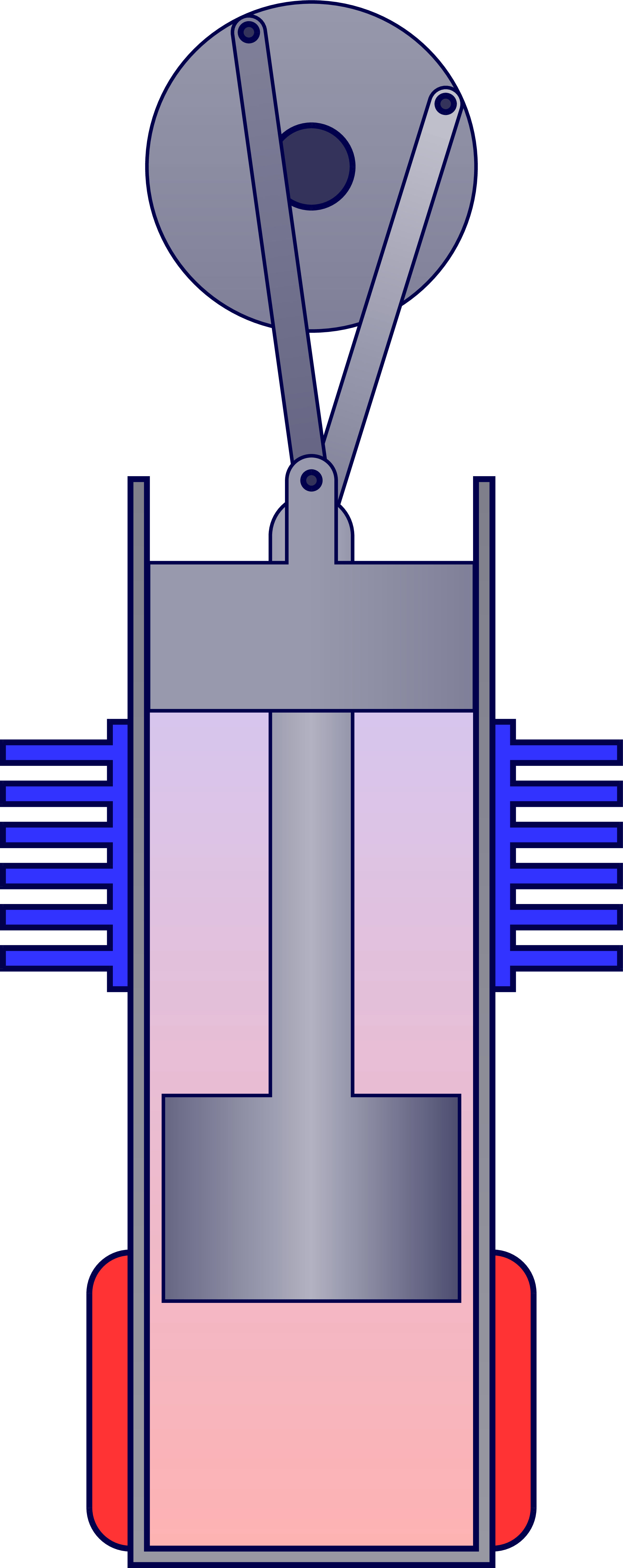
% 1
\begin{tikzpicture}
\engine{110};
\draw[vector] (195:1.4*\R) arc (195:140:1.4*\R);
\node[below left=3,align=right,scale=2.5] at (C-1) {cold\\[-.5mm]end};
\node[below left=3,align=right,scale=2.5] at (H-1) {hot\\[-.5mm]end};
\node[right=2,align=left,scale=2.5] at (20:1.1*\R) {fly\\[-.5mm]wheel};
\draw[arrow] (L) ++ (-.6,-.1) --++ (10:2)
node[right=-2,align=right,scale=2.4] {loosely\\[-.5mm]fitting\\[-.5mm]piston};
\end{tikzpicture}
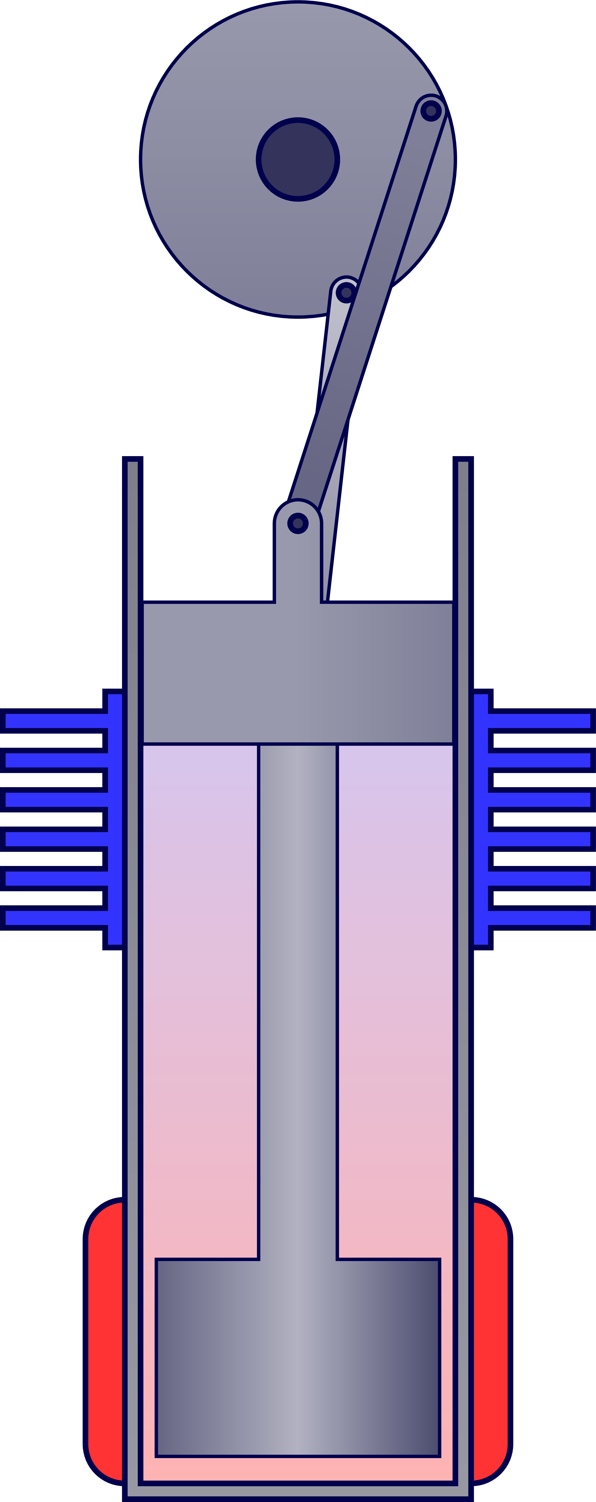
% 2
\begin{tikzpicture}
\engine{25};
\end{tikzpicture}
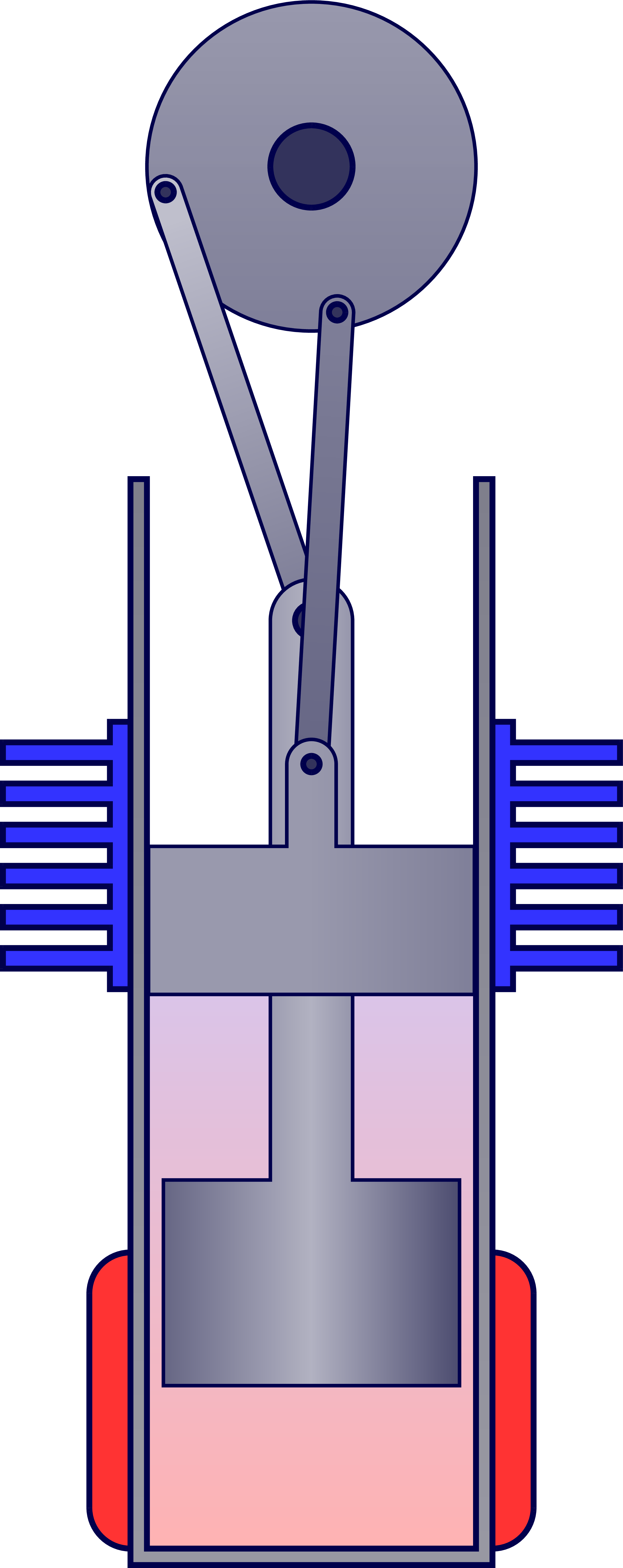
% 3
\begin{tikzpicture}
\engine{-70};
\end{tikzpicture}
% 4
\begin{tikzpicture}
\engine{-170};
\end{tikzpicture}
\end{document}Click to download: engine_stirling_beta.tex • engine_stirling_beta.pdf
Open in Overleaf: engine_stirling_beta.tex