")


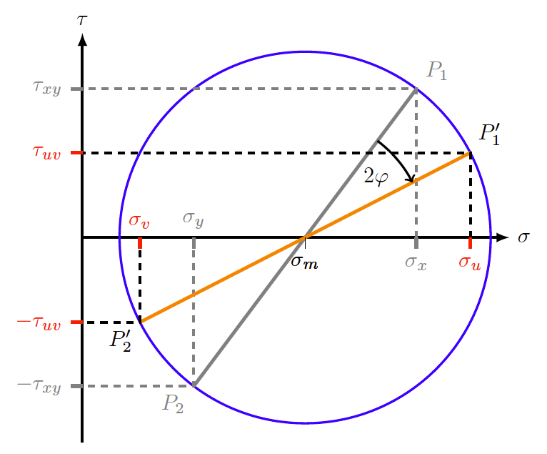
Draws Mohr’s circle for given stress – values before and after rotation.
Inputs are the stress – values and the angle of rotation.
Version 1, 29.07.2023
\documentclass[tikz,border=10pt]{standalone}
\usetikzlibrary{calc}
\tikzset{prerot/.style = {line width = 1.5pt, color = gray},
        postrot/.style = {line width = 1.5pt, color = red},
  reflineprerot/.style = {line width = 1.pt,  color = gray, dashed},
 reflinepostrot/.style = {line width = 1.pt,  color = black, dashed}}
\begin{document}
\begin{tikzpicture}[scale=0.6]
%Choose stress values
\def\sigmax{9} % upper normal-stress value before rotation
\def\sigmay{3} % lower normal-stress value before rotation
\def\tauxy{4}  % shear-stress value before rotation
\def\phi{13}   % angle for rotation
\pgfmathsetmacro\sigmam{0.5*(\sigmax+\sigmay)} % compute center of circle
\pgfmathsetmacro\sigmad{0.5*(\sigmax-\sigmay)} % compute x-component of radius
\pgfmathsetmacro\r{sqrt((\sigmad)^2+\tauxy^2)} % compute radius of circle
% compute upper normal-stress value after rotation:
\pgfmathsetmacro\sigmau{\sigmam+\sigmad*cos(2*\phi)+\tauxy*sin(2*\phi)}
% compute lower normal-stress value after rotation:
\pgfmathsetmacro\sigmav{\sigmam-\sigmad*cos(2*\phi)-\tauxy*sin(2*\phi)}
% compute shear-stress value after rotation:
\pgfmathsetmacro\tauuv{-\sigmad*sin(2*\phi)+\tauxy*cos(2*\phi)}
\def\s{0.5} % parameter for small offsets
\pgfmathsetmacro\w{\sigmam+\r+\s} % parameter for width
\pgfmathsetmacro\h{\r+\s} % parameter for height
%
%\draw[step=0.5,gray] (-4*\s,-\h) grid (\w+\s,\h+\s);% turn on grid if wanted
%
% coordinate system
\draw[line width = 1pt,-latex] (0,-\h)--(0,\h)
  node[at end, anchor = south] {$\tau$};
\draw[line width = 1pt,-latex] (0,0)--(\w,0)
  node[at end, anchor = west] {$\sigma$};
%
% draw circle
\draw[color = blue, line width = 1pt] (\sigmam,0) circle (\r);
%
% draw system before rotation
% draw connecting line
\draw[prerot](\sigmax,\tauxy) - -(\sigmay,-\tauxy);
\node at (\sigmax,\tauxy)  [anchor=south west, prerot] {$P_1$};
\node at (\sigmay,-\tauxy) [anchor=north east, prerot] {$P_2$};
%
% draw stress values
\draw[reflineprerot] (\sigmax,0) -- +(0,\tauxy)  -- (0,\tauxy);
\draw[reflineprerot] (\sigmay,0) -- +(0,-\tauxy) -- (0,-\tauxy);
\draw[prerot](0,\tauxy)     -- +(-0.3,0) node[anchor = east] {$\tau_{xy}$};
\draw[prerot](0,-\tauxy)    -- +(-0.3,0) node[anchor = east] {$-\tau_{xy}$};
\draw[prerot](\sigmax,0)    -- +(0,-0.3) node[anchor = north] {$\sigma_x$};
\draw[prerot](\sigmay,-0.3) -- +(0,0.3)  node[anchor = south] {$\sigma_y$};
\draw (\sigmam,0) --+(0,-0.3) node[anchor = north] {$\sigma_m$};
% draw system before rotation
%
% draw connecting line
\draw[line width = 1.5pt,color=orange] (\sigmau,\tauuv) -- (\sigmav,-\tauuv);
\node at (\sigmau,\tauuv) [anchor=south west] {$P_1^{\prime}$};
\node at (\sigmav,-\tauuv) [anchor=north east] {$P_2^{\prime}$};
%
% draw stress values
\draw[reflinepostrot] (\sigmau,0) -- +(0,\tauuv)  -- (0,\tauuv);
\draw[reflinepostrot] (\sigmav,0) -- +(0,-\tauuv) -- (0,-\tauuv);
\draw[postrot] (0,\tauuv)     -- +(-0.3,0) node[anchor = east]  {$\tau_{uv}$};
\draw[postrot] (0,-\tauuv)    -- +(-0.3,0) node[anchor = east]  {$-\tau_{uv}$};
\draw[postrot] (\sigmau,0)    -- +(0,-0.3) node[anchor = north] {$\sigma_u$};
\draw[postrot] (\sigmav,-0.3) -- +(0,0.3)  node[anchor = south] {$\sigma_v$};
\draw (\sigmam,0) -- +(0,-0.3) node[anchor = north] {$\sigma_m$};
%
% mark angle
\pgfmathsetmacro{\psi}{atan2(\tauxy,\sigmad)}
\pgfmathsetmacro{\alpha}{\psi-\phi}
\pgfmathsetmacro{\beta}{\psi-2*\phi}
\draw[line width=1pt, color = black,->] ($(\sigmam,0)+(\psi:0.65*\r)$)
  arc(\psi:\beta:0.65*\r)
  node[anchor=center] at ($(\sigmam,0)+(\alpha:0.5*\r)$) {$2\varphi$};
\end{tikzpicture}
\end{document}