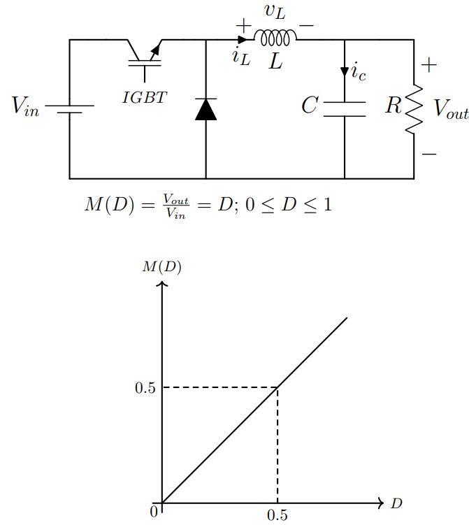
% Buck Converter
% This DC-DC converter decreases the voltage level from input to output

% Designed by: Amir Ostadrahimi

\documentclass [border=5pt]{standalone}
\usepackage{tikz}
\usepackage[american,cuteinductors,smartlabels]{circuitikz} % A package to draw electrical networks with TikZ

%-- the dimensions of the elements can be changed here
\ctikzset{bipoles/thickness=0.7}
\ctikzset{bipoles/length=1.5cm}
\ctikzset{bipoles/resistor/width=0.7}
\ctikzset{bipoles/resistor/height=0.25}
\ctikzset{bipoles/diode/height=0.3}
\ctikzset{bipoles/diode/width=0.3}
\ctikzset{tripoles/thickness=0.7}
\ctikzset{bipoles/battery1/height=0.7}

%settings for fonts and lines
\tikzstyle{every node}=[font=\Large]
\tikzstyle{every path}=[line width=0.9 pt, line cap=round, line join=round]


\begin{document}

 \begin{circuitikz}

%------ Converter
\coordinate  (VBottom) at (0,0); %%VBottom stands for voltage source bottom and is located on (0,0)

\draw (VBottom) to [battery1, l=$V_{in}$, invert] ++(0,3) coordinate (VTop); % "battery1" is to insert voltage source, instead of it, you can use "battery", "battery2", or "V".
% the " l=$V_{in}$" is for label. You can use  "l_=$V_{in}$" or "l^=$V_{in}$" to change its location.
%"invert" changes the polarity of the source. (VTop) stands for voltage top.
% to change size of the voltage source, we can modify "\ctikzset{bipoles/battery1/height=0.7}", at the beginning of the documents

\draw (VTop) to [short] ++(0.8,0) node [nigbt, anchor=C, rotate=90, label={[yshift=-1.5 cm] \normalsize $IGBT$}] (nigbt1){}; % here we used an N-channel IGBT using "nigbt". Alternatively, we could use "pigbt", "nmos", "pmos" and so on.


\draw (nigbt1.E) to [short]++(0.5,0) coordinate (DiodeTop) to [short]++(0.5,0) to [L, l_=$L$, v^=$v_L$, i>_=$i_L$]++ (2,0) coordinate (InductorRight);  % "i>_=$i_L$ " is for showing the current of the element, by using "^" we can change its location and bring it at the input and the output of the element. By using  "<"  and  ">"  we can change its direction. And finally by using "_" we can change its vertical location. Using "coordinate (DiodeTop) " we considered a connection point to the diode.

\draw   (DiodeTop) to [D*, invert] (DiodeTop|-VBottom); %Using  " (DiodeTop|-VBottom)" the diode will be continued till the intersection of the vertical line from (DiodeTop) and the horizontal line from (VBottom). Here, "invert" is used to change the direction of the diode and "*" is used to change type of the diode to filled-black diode

\draw (InductorRight) to [short]++(0.5,0)  coordinate (CapacitorTop) to [C, l_=$C$, i>^=$i_c$](CapacitorTop|-VBottom);  %Using  " (CapacitorTop|-VBottom)" the diode will be continued till the intersection of the vertical line from (CapacitorTop) and the horizontal line from (VBottom)

\draw  (CapacitorTop) to [short]++(1.5,0)  coordinate (ResistorTop) to [R, l_=$R$, v^=$V_{out}$](ResistorTop|-VBottom) coordinate (ResistorBottom)

(ResistorBottom)-- (VBottom);


%------ Conversion Ratio

\coordinate [label={ [xshift=0, yshift=0] \large $ M(D)=\frac{V_{out}}{V_{in}}=D;$ \large $0 \leq D \leq 1$ }] (M) at (3,-1);

%%------ Curve

\def\xo{2} % Axes of origin
\def\yo{-7} % Axes of origin
\def\length {5} % length of the axes
\def\N{200} %number of samples

\coordinate [label={ [xshift=-5, yshift=-12]  \normalsize$0$ }] (origin) at (\xo,\yo); %

\draw[->] (\xo -0.2, \yo) --++(\length,0) node[right] {\small $D$};
 \draw[->]  (\xo,\yo -0.2) -- ++(0, \length) node[above] {\small $M(D)$};
\draw     plot[samples=\N, domain=  0     :  4, xshift=\xo cm, yshift=\yo cm] (\x  ,\x);

\draw (\xo , \yo)++(2.5,0) node [below] (halfx){\normalsize $0.5$};
\draw (\xo , \yo)++(0,2.5) node [left] (halfy){\normalsize $0.5$};
\draw [dashed] (halfx)|-(halfy);

\end{circuitikz}


\end{document}
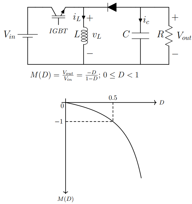
Buck-Boost Converter
% Buck-Boost Converter
% This DC-DC converter could decrease or increase the voltage level from input to output

% Designed by: Amir Ostadrahimi

\documentclass [border=5pt]{standalone}
\usepackage{tikz}
\usepackage[american,cuteinductors,smartlabels]{circuitikz}

%-- the dimensions of the elements can be changed here
\ctikzset{bipoles/thickness=0.7}
\ctikzset{bipoles/length=1.5cm}
\ctikzset{bipoles/resistor/width=0.7}
\ctikzset{bipoles/resistor/height=0.25}
\ctikzset{bipoles/diode/height=0.3}
\ctikzset{bipoles/diode/width=0.3}
\ctikzset{tripoles/thickness=0.7}
\ctikzset{bipoles/battery1/height=0.7}

%settings for fonts and lines
\tikzstyle{every node}=[font=\Large]
\tikzstyle{every path}=[line width=0.9 pt, line cap=round, line join=round]


\begin{document}

 \begin{circuitikz}

%------ Converter
\coordinate  (VBottom) at (0,0);

\draw (VBottom) to [battery1, l=$V_{in}$, invert] ++(0,3) coordinate (VTop);

\draw (VTop) to [short] ++(0.8,0) node [nigbt, anchor=C, rotate=90, label={[yshift=-1.5 cm] \normalsize $IGBT$}] (nigbt1){};

\draw (nigbt1.E) to [short]++(0.5,0) coordinate (InductorTop) to [short]++(0.5,0) to [D*, invert] ++(2,0) coordinate (DiodeRight);

\draw (InductorTop)  to [L, l_=$L$, v^=$v_L$, i>_=$i_L$] (InductorTop|-VBottom);

\draw (DiodeRight) to [short]++(0.5,0)  coordinate (CapacitorTop) to [C, l_=$C$, i>^=$i_c$](CapacitorTop|-VBottom);

\draw  (CapacitorTop) to [short]++(1.5,0)  coordinate (ResistorTop) to [R, l_=$R$, v^=$V_{out}$](ResistorTop|-VBottom) coordinate (ResistorBottom)

(ResistorBottom)-- (VBottom);


%------ Conversion Ratio

\coordinate [label={ [xshift=0, yshift=0] \large $ M(D)=\frac{V_{out}}{V_{in}}=\frac{-D}{1-D};$ \large $0 \leq D <1$ }] (M) at (3,-1);

%%------ Curve

\def\xo{2} % Axes of origin
\def\yo{-2} % Axes of origin
\def\length {5} % length of the axes
\def\N{200} %number of samples

\coordinate [label={ [xshift=-5, yshift=-12]  \normalsize$0$ }] (origin) at (\xo,\yo); %

\draw[->] (\xo -0.2, \yo) --++(\length,0) node[right] {\small $D$};
 \draw[->]  (\xo,\yo +0.2) -- ++(0, -\length) node[below] {\small $M(D)$};
\draw     plot[samples=\N, domain=  0     :  0.8 , xshift=\xo cm, yshift=\yo cm] (5*\x  ,{-\x/(1-\x)});

\draw (\xo , \yo)++(2.5,0) node [above] (half){\normalsize $0.5$};
\draw (\xo , \yo)++(0,-1) node [left] (minus-one){\normalsize $-1$};
\draw [dashed] (half)|-(minus-one);

\end{circuitikz}

\end{document}
")