MPPT- a single PV connected to a generic converter and load 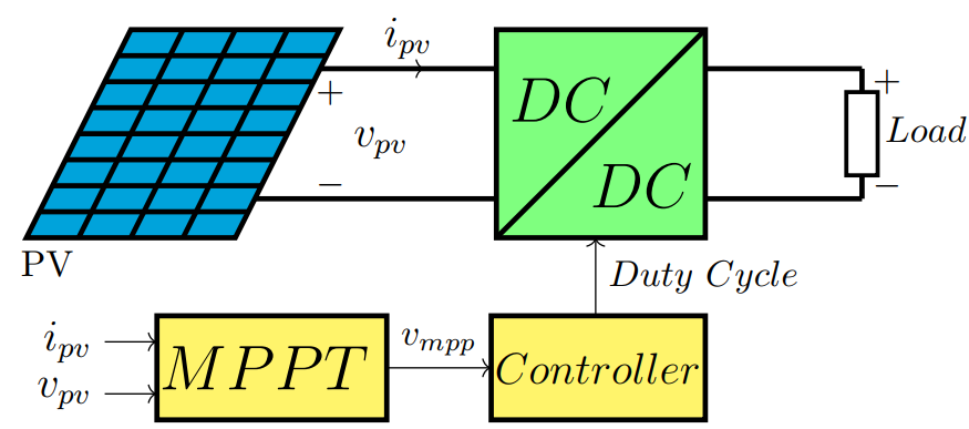
% Maximum Power Point Tracking (MPPT) for a single PV module
% Generic converter and load
%Author: Amir Ostadrahimi

\documentclass[border=3pt]{standalone}

\usepackage[american,cuteinductors,smartlabels]{circuitikz} % A package to draw electrical circuits with TikZ

%-- the dimensions of the elements can be changed here
\ctikzset{bipoles/thickness=0.8}
\ctikzset{bipoles/length=1cm}

\begin{document}
\begin{circuitikz}


%####---------------Panel-----------------
%%------------Frame--------------
\draw (0,0) coordinate (P1);
\draw (P1)++(2,0) coordinate(P2);
\draw (P1)++(-1,-2) coordinate (P3);
\draw (P3)++(2,0) coordinate(P4);
\draw [line width=.5mm, fill=cyan!90!black] (P1)--(P2)--(P4)--(P3)--cycle;


%%---------------Vertical Lines-----------------
\draw [line width=.5mm] (P1)++ (-.125,-0.25)--(1.875,-.25) ;
\draw [line width=.5mm] (P1)++ (-.25,-0.5)--(1.75,-.5)  ;
\draw [line width=.5mm] (P1)++ (-.375,-0.75)--(1.625,-.75) ;
\draw [line width=.5mm] (P1)++ (-.5,-1)--(1.5,-1) ;
\draw [line width=.5mm] (P1)++  (-.625,-1.25)--(1.375,-1.25) ;
\draw [line width=.5mm] (P1)++ (-.75,-1.5)--++(2,0)  ;
\draw [line width=.5mm] (P1)++  (-.875,-1.75)--++(2,0) coordinate (P34) ;


%%--------------Horizontal Line-----------------

\draw [line width=.5mm] (.5,0)--++(-1,-2);

\draw [line width=.5mm] (1,0)--++(-1,-2);

\draw [line width=.5mm] (1.5,0)--++(-1,-2);

\draw (P3)++(0.2,-0.25) coordinate (Pname);
\node (PVname) at (Pname) {PV};


%#####----------------Converter----------

\draw [line width=.5mm] (P2)++(1.5,0) coordinate(C1);
\draw (C1)++(2,0) coordinate (C2);
\draw (C1)++(0,-2) coordinate (C3);
\draw (C3)++(2,0) coordinate (C4);

\draw  [line width=.5mm, fill=green!50] (C1)-- (C3)--(C4)--(C2)--cycle;
\draw [line width=.5mm] (C3)--(C2);

%%---------------------------------------

\draw (1.8125,-.375)  coordinate(conn1) ;
\draw (P4)++(.125,.25)--++(.0625,.125) coordinate(conn2) ;
\draw (conn1)++(.1,-.05) coordinate(VPV);


%%--------Connection of Panel and coverter
%%---------------------------------------
\draw (conn1-|C1) coordinate(connC1);
\draw (conn2-|C1) coordinate(connC2);

\draw [->](conn1)--++(1,0);
\draw [line width=.5mm] (conn1) to [short,l=\large$i_{pv}$](connC1);
\draw (VPV) to [open, l=\large$ v_{pv}$, v^=$ $]++(0,-1.25);
\draw [line width=.5mm] (conn2) --(connC2);
%%---------------------------------------


%####------------Controller--------

\draw (C3)++(-0.05,-.75) coordinate(Cont1);

\draw  [line width=.5mm] (Cont1)++(2.05,0) coordinate(Cont2);

\draw (Cont2)++(0,-1) coordinate (Cont4);
\draw (Cont1)++(0,-1) coordinate(Cont3);

\draw [line width=.5mm, fill=yellow!70] (Cont1)--(Cont2)--(Cont4)--(Cont3)--cycle;

\draw (Cont1)++(1,0) coordinate (ContM);
\draw [->] (ContM) --++(0,0.75);

\draw (Cont4)++(0,.5) coordinate (ContV); %% Joint of Vout
\draw (ContV)++(.5,0) coordinate[right] (Vo) ;


%####-------MPPT--------

\draw (Cont1)++(0,-.5) coordinate (Vm2);
\draw (Vm2)++(-1,0) coordinate (Vm1);
\draw (Vm1)++(0.5,0) node [above] (Vmpp){$v_{mpp}$};

\draw [->](Vm1)--(Vm2);

%%-------- MPPT Box
\draw (Vm1)++(0,0.5) coordinate (MP2);
\draw (Vm1)++(0,-0.5) coordinate (MP4);
\draw (MP2)++(-2.2,0) coordinate (MP1);
\draw (MP4)++(-2.2,0) coordinate (MP3);

\draw [line width=.5mm , fill=yellow!70] (MP1)--(MP2)--(MP4)--(MP3)--cycle;
%-----------------------

\draw (MP1)++(0,-0.25) coordinate (MP11);
\draw (MP11)++(-0.5,0) coordinate (MP12);
\draw [->] (MP12)--(MP11);
\node [left] (MP122) at (MP12) {\large$i_{pv}$};

\draw (MP3)++(0,0.25) coordinate (MP31);
\draw (MP31)++(-0.5,0) coordinate (MP32);
\draw [->] (MP32)--(MP31);
\node [left] (MP322) at (MP32) {\large$v_{pv}$};


%####-----------Text-----------------

\draw (connC1)++(0,-.3) coordinate (T1);

\node [below, right](Text1) at (T1) {\LARGE $DC$};

\draw (C4)++(0,0.5) coordinate (T2);

\node [above, left](Text1) at (T2) {\LARGE$ DC$};

\draw (Cont1)++(1.02,-0.5) coordinate(T3);

\node (Text3) at (T3) {\large $Controller$ };

\draw (Vm1)++(-2.3,0) coordinate (MPM);
\node [right] (Spl) at (MPM) {\LARGE $MPPT$};


\draw (ContM)++(0, 0.375) coordinate (ContM2);
\node [right] (Duty) at (ContM2) {$Duty$ $Cycle$};


\draw (C2)++(0,-1) coordinate (CM); %middle of converter at right side
\draw (CM)++(1.25,0) coordinate (Vot);

%%--------------------------
\draw (conn1-|C2) coordinate(connCL1); %Joint of Converter with Vout connections
\draw (conn2-|C2) coordinate(connCL2); %Joint of Converter with Vout connections
%%--------------------------

\draw [line width=.5mm] (connCL1) to [short]++(1.5,0) coordinate (out1);
\draw [line width=.5mm] (connCL2) to [short]++(1.5,0) coordinate (out2);
\draw [line width=.5mm]  (out1) to [generic, v^=$ $, l=$Load$](out2);


\end{circuitikz}

\end{document}
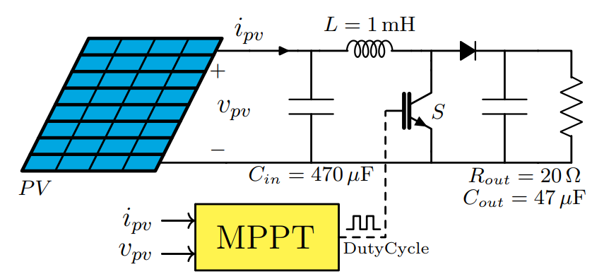
MPPT- A single PV connected to a boost converter and a resistive load
% Maximum Power Point Tracking (MPPT) for a single PV module
% for a boost converter and a resistive load
%Author: Amir Ostadrahimi

\documentclass [border=5pt]{standalone}

\usepackage{tikz}
\usepackage[american,cuteinductors,smartlabels]{circuitikz} % A package to draw electrical circuits with TikZ
\usepackage{siunitx} %A comprehensive (si) units package; See: https://texdoc.org/serve/siunitx/0


%-- the dimensions of the elements can be changed here
\ctikzset{bipoles/thickness=0.8}
\ctikzset{bipoles/length=1.1cm}
\ctikzset{bipoles/diode/height=.25}
\ctikzset{bipoles/diode/width=.2}
\tikzstyle{every node}=[font=\small]
\tikzstyle{every path}=[line width=0.8pt,line cap=round,line join=round]

\begin{document}


\begin{circuitikz}


%####----------Panel-----------------

%%------------Frame--------------
\draw (0,0) coordinate (P1);
\draw (P1)++(2,0) coordinate(P2);
\draw (P1)++(-1,-2) coordinate (P3);
\draw (P3)++(2,0) coordinate(P4);
\draw [line width=.5mm, fill=cyan!93!black] (P1)--(P2)--(P4)--(P3)--cycle;

%%---------------Vertical Lines-----------------
\draw [line width=.5mm] (P1)++ (-.125,-0.25)--(1.875,-.25) ;
\draw [line width=.5mm] (P1)++ (-.25,-0.5)--(1.75,-.5)  ;
\draw [line width=.5mm] (P1)++ (-.375,-0.75)--(1.625,-.75) ;
\draw [line width=.5mm] (P1)++ (-.5,-1)--(1.5,-1) ;
\draw [line width=.5mm] (P1)++  (-.625,-1.25)--(1.375,-1.25) ;
\draw [line width=.5mm] (P1)++ (-.75,-1.5)--++(2,0)  ;
\draw [line width=.5mm] (P1)++  (-.875,-1.75)--++(2,0) coordinate (P34) ;


%%--------------Horizontal Line-----------------

\draw [line width=.3mm] (.5,0)--++(-1,-2);

\draw [line width=.3mm] (1,0)--++(-1,-2);

\draw [line width=.3mm] (1.5,0)--++(-1,-2);

\draw (P3)++(0.2,-0.25) coordinate (Pname);
\node (PVname) at (Pname) {$PV$};

%%---------------------------------------

\draw (1.9375,-. -0.1875)  coordinate(conn1);
\draw (P4)++(0,0)--++(.0625,.125) coordinate(conn2) ;
\draw (conn1)++(0,-.05) coordinate(VPVin);
\draw (VPVin) to [open,  v^=$ $]++(0,-1.7);
\draw(VPVin)++(0.25, -0.85) node (VPVname){\large$ v_{pv}$};

%%--------Connection of Panel and coverter

\draw   [line width=.3mm] (conn1) to [short, l=\large$i_{pv}$]++(0.95,0)to [short, i^=$ $]++(0.05,0) to [short]++(0.4,0) coordinate (connCin);
\draw  [line width=.3mm](conn2) to [short]++(2,0) -- (conn2-|connCin) coordinate (connCin2);
\draw  [line width=.3mm] (connCin) to[C] (connCin2);
%-----------------------------------------
\draw  [line width=.3mm] (connCin) to [short] ++(0.25,0) to [L,l={$L=\SI{1}{\milli \henry}$}]++(1.25,0)coordinate (connL);
\draw   [line width=.3mm] (connL) to [short] ++(.3,0) coordinate(D1);
\draw [line width=.3mm] (D1) to [short]++(0,-.3)  node [nigbt, anchor=C , label={[xshift=3, yshift=-7] $S$ }] (nigbt1){} ;
\draw [line width=.3mm] (nigbt1.E)|-(connCin2);
\draw  [line width=.3mm] (D1) to [D*] ++(1.1,0) coordinate(out1);
\draw  [line width=.3mm] (out1) to [C](out1|-connCin2) coordinate (out2);
\draw  [line width=.3mm] (out2) to [short]++(1,0) coordinate (Rout2);
\draw  [line width=.3mm] (out1) to [short]++(1,0) coordinate (Rout1) to [R](Rout2);
\draw  [line width=.3mm] (out2)--++(-1.1,0);


%%---------------------------------------------------------
\draw (connCin2)++(0,-.2) node (Write2){$C_{in}= \SI{470}{\mu \farad} $};
\draw (out2)++(.3,-.2) node (Write2){$R_{out}= \SI{20}{\ohm}$};
\draw (out2)++(.3,-.55) node (Write3){$C_{out}= \SI{47}{\mu \farad}$};
%%---------------------------------------------------------

%####-------------MPPT Box------------------------


\draw [line width=.3mm, fill=yellow!80] (1.6, -2.5) coordinate (M1)--++(2.15,0) coordinate(M2)--++(0,-1) coordinate(M3)--++(-2.15,0) coordinate (M4)--cycle;
\draw (M2)++(0,-.5) coordinate (Dout);

%%---DashedLine---
\draw [line width=.3mm, dashed](Dout)--++(0.7,0)--++(0,1.9);

%%-----Pulse
\draw (Dout)++(0.12,0.12) coordinate (pulse);
\draw (pulse) --++(0.1,0)--++(0,0.2)--++(0.1,0)--++(0,-.2)--++(0.1,0)--++(0,0.2)--++(0.1,0)--++(0,-.2)--++(.1,0);

%%---- DutyCyle---
\draw (Dout)++(0.71,-0.18) node (Duty){\scriptsize  DutyCycle};


%%----CCMPPT---
\draw (Dout)++(-1.1,0) node (Duty){ \Large MPPT};

%%--- Input Ipv and Vpv---

\draw (M1) --++(0,-0.25) coordinate (IPV);
\draw (IPV)--++(-0.5,0) node [anchor=east]  (IPV1) {\large$i_{pv}$};
\draw [->] (IPV1)--(IPV);

\draw (M4) --++(0,0.25) coordinate (VPV);
\draw (VPV)--++(-0.5,0) node [anchor=east] (VPV1) {\large$v_{pv}$};
\draw [->] (VPV1)--(VPV);

\end{circuitikz}
\end{document}
")

