")


Edit and compile if you like:
\documentclass{article}
\usepackage{tikz}
\usepackage{tikz-3dplot}
\usetikzlibrary{math}
\usepackage[active,tightpage]{preview}
\PreviewEnvironment{tikzpicture}
\setlength\PreviewBorder{0.125pt}
%
% File name: directional-angles.tex
% Description:
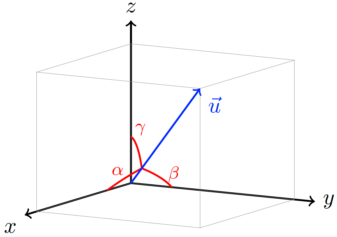
% The directional angles of a vector are geometrically represented.
%
% Date of creation: July, 25th, 2021.
% Date of last modification: October, 9th, 2022.
% Author: Efra�n Soto Apolinar.
% https://www.aprendematematicas.org.mx/author/efrain-soto-apolinar/instructing-courses/
% Source: page 11 of the
% Glosario Ilustrado de Matem\'aticas Escolares.
% https://tinyurl.com/5udm2ufy
%
% Terms of use:
% According to TikZ.net
% https://creativecommons.org/licenses/by-nc-sa/4.0/
% Your commitment to the terms of use is greatly appreciated.
%
\begin{document}
\tdplotsetmaincoords{80}{120}
%
\begin{tikzpicture}[tdplot_main_coords,scale=0.75]
% Indicate the components of the vector in rectangular coordinates
\pgfmathsetmacro{\ux}{4}
\pgfmathsetmacro{\uy}{4}
\pgfmathsetmacro{\uz}{3}
% Length of each axis
\pgfmathsetmacro{\ejex}{\ux+0.5}
\pgfmathsetmacro{\ejey}{\uy+0.5}
\pgfmathsetmacro{\ejez}{\uz+0.5}
\pgfmathsetmacro{\umag}{sqrt(\ux*\ux+\uy*\uy+\uz*\uz)} % Magnitude of vector $\vec{u}$
% Compute the angle $\theta$
\pgfmathsetmacro{\angthetax}{pi*atan(\uy/\ux)/180}
\pgfmathsetmacro{\angthetay}{pi*atan(\ux/\uz)/180}
\pgfmathsetmacro{\angthetaz}{pi*atan(\uz/\uy)/180}
% Compute the angle $\phi$
\pgfmathsetmacro{\angphix}{pi*acos(\ux/\umag)/180}
\pgfmathsetmacro{\angphiy}{pi*acos(\uy/\umag)/180}
\pgfmathsetmacro{\angphiz}{pi*acos(\uz/\umag)/180}
% Compute rho sin(phi) to simplify computations
\pgfmathsetmacro{\costz}{cos(\angthetax r)}
\pgfmathsetmacro{\sintz}{sin(\angthetax r)}
\pgfmathsetmacro{\costy}{cos(\angthetay r)}
\pgfmathsetmacro{\sinty}{sin(\angthetay r)}
\pgfmathsetmacro{\costx}{cos(\angthetaz r)}
\pgfmathsetmacro{\sintx}{sin(\angthetaz r)}
% Coordinate axis
\draw[thick,->] (0,0,0) -- (\ejex,0,0) node[below left] {$x$};
\draw[thick,->] (0,0,0) -- (0,\ejey,0) node[right] {$y$};
\draw[thick,->] (0,0,0) -- (0,0,\ejez) node[above] {$z$};
% Projections of the components in the axis
\draw[gray,very thin,opacity=0.5] (0,0,0) -- (\ux,0,0) -- (\ux,\uy,0) -- (0,\uy,0) -- (0,0,0); % face on the plane z = 0
\draw[gray,very thin,opacity=0.5] (0,0,\uz) -- (\ux,0,\uz) -- (\ux,\uy,\uz) -- (0,\uy,\uz) -- (0,0,\uz); % face on the plane z = \uz
\draw[gray,very thin,opacity=0.5] (0,0,0) -- (0,0,\uz) -- (\ux,0,\uz) -- (\ux,0,0) -- (0,0,0); % face on the plane y = 0
\draw[gray,very thin,opacity=0.5] (0,\uy,0) -- (0,\uy,\uz) -- (\ux,\uy,\uz) -- (\ux,\uy,0) -- (0,\uy,0); % face on the plane y = \uy
\draw[gray,very thin,opacity=0.5] (0,0,0) -- (0,\uy,0) -- (0,\uy,\uz) -- (0,0,\uz) -- (0,0,0); % face on the plane x = 0
\draw[gray,very thin,opacity=0.5] (\ux,0,0) -- (\ux,\uy,0) -- (\ux,\uy,\uz) -- (\ux,0,\uz) -- (\ux,0,0); % face on the plane x = \ux
% Arc indicating the angle $\alpha$
% (angle formed by the vector $\vec{v}$ and the $x$ axis)
\draw[red,thick] plot[domain=0:\angphix,smooth,variable=\t] ({cos(\t r)},{sin(\t r)*\costx},{sin(\t r)*\sintx});
% Arc indicating the angle $\beta$
% (angle formed by the vector $\vec{v}$ and the $y$ axis)
\draw[red,thick] plot[domain=0:\angphiy,smooth,variable=\t] ({sin(\t r)*\sinty},{cos(\t r)},{sin(\t r)*\costy});
% Arc indicating the angle $\gamma$
% (angle formed by the vector $\vec{v}$ and the $z$ axis)
\draw[red,thick] plot[domain=0:\angphiz,smooth,variable=\t] ({sin(\t r)*\costz},{sin(\t r)*\sintz},{cos(\t r)});
% Vector $\vec{u}$
\draw[blue,thick,->] (0,0,0) -- (\ux,\uy,\uz) node [below right] {$\vec{u}$};
% Nodes indicating the direction angles
\pgfmathsetmacro{\xa}{1.85*cos(0.5*\angphix r)}
\pgfmathsetmacro{\ya}{1.85*sin(0.5*\angphix r)*\costx}
\pgfmathsetmacro{\za}{1.85*sin(0.5*\angphiz r)*\sintx}
\node[red] at (\xa,\ya,\za) {\footnotesize$\alpha$};
%
\pgfmathsetmacro{\xb}{1.5*sin(0.5*\angphiy r)*\sinty}
\pgfmathsetmacro{\yb}{1.5*cos(0.5*\angphiy r)}
\pgfmathsetmacro{\zb}{1.5*sin(0.5*\angphiy r)*\costy}
\node[red] at (\xb,\yb,\zb) {\footnotesize$\beta$};
%
\pgfmathsetmacro{\xc}{1.5*sin(0.5*\angphiz r)*\costz}
\pgfmathsetmacro{\yc}{1.5*sin(0.5*\angphiz r)*\sintz}
\pgfmathsetmacro{\zc}{1.5*cos(0.5*\angphiz r)}
\node[red] at (\xc,\yc,\zc) {\footnotesize$\gamma$};
%
\end{tikzpicture}
%
\end{document}
Click to download: directional-angles.tex • directional-angles.pdf
Open in Overleaf: directional-angles.tex
See more on the author page of Efraín Soto Apolinar.