")


Edit and compile if you like:
% Author: Izaak Neutelings (October 2020)
\documentclass[border=3pt,tikz]{standalone}
\usepackage{physics}
\usepackage{tikz}
\usetikzlibrary{calc}
\usetikzlibrary{angles,quotes} % for pic
\usetikzlibrary{arrows.meta}
\usetikzlibrary{patterns}
\tikzset{>=latex} % for LaTeX arrow head
\colorlet{xcol}{blue!70!black}
\colorlet{vcol}{green!60!black}
\colorlet{myred}{red!65!black}
\colorlet{mypurple}{blue!60!red!80}
\colorlet{acol}{red!50!blue!80!black!80}
\tikzstyle{rvec}=[->,xcol,very thick,line cap=round]
\tikzstyle{vvec}=[->,vcol,very thick,line cap=round]
\tikzstyle{myarr}=[{Latex[length=3,width=3]}-,xcol]
\tikzstyle{force}=[->,myred,very thick,line cap=round]
\tikzstyle{mass}=[line width=0.6,draw=red!30!black, %rounded corners=1,
top color=red!40!black!30,bottom color=red!40!black!10,shading angle=30]
\tikzstyle{ground}=[preaction={fill,top color=black!10,bottom color=black!5,shading angle=20},
fill,pattern=north east lines,draw=none,minimum width=0.3,minimum height=0.6]
\tikzstyle{metal}=[fill,top color=black!40,bottom color=black!20,shading angle=10]
\begin{document}
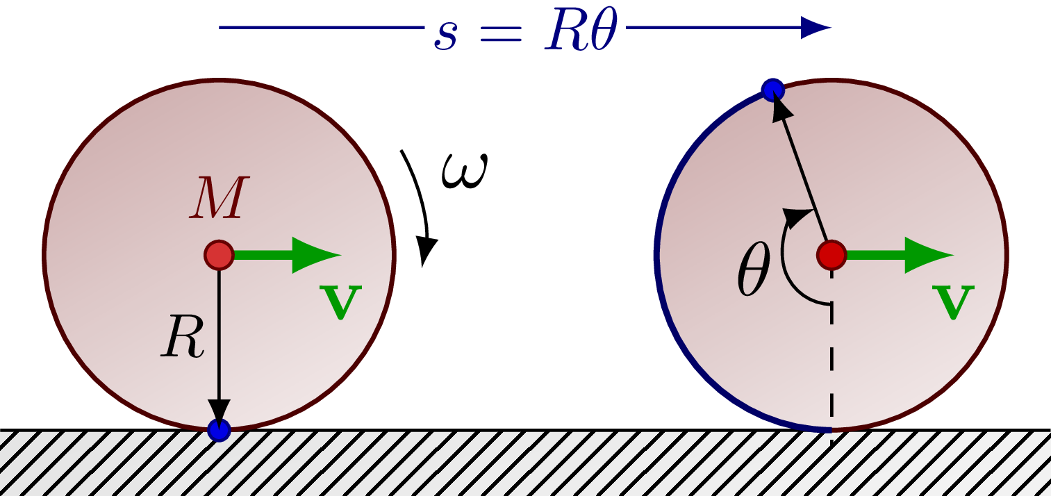
% ROLLING
\begin{tikzpicture}
\def\W{4.8} % ground width
\def\H{3.2} % ground height
\def\D{0.3} % ground depth
\def\R{0.8} % disk radius
\def\d{1.0} % disks' distances from edge
\def\angb{{(2*\d-\W)*180/pi-90}} % angle point 2
\coordinate (A) at (\d,\R); % disk 1 origin
\coordinate (B) at (\W-\d,\R); % disk 2 origin
\coordinate (RA) at ($(A)+(-90:\R)$); % point 1
\coordinate (RB) at ($(B)+(\angb:\R)$); % point 2
\coordinate (BB) at ($(B)+(-90:\R)$); % point 2 bottom
% GROUND
\draw[ground] %(0,0) rectangle++ (-\D,\H) (-\D,\H) rectangle++ (\W,\D);
(0,0) rectangle++ (\W,-\D);
\draw (0,0) --++ (\W,0);
% DISK 1
\draw[mass] (A) circle(\R);
\draw[blue!50!black,fill=blue!90!black] (RA) circle(0.06*\R);
\draw[->] (A) -- (RA) node[midway,above=1,left=-1,scale=0.8] {$R$}; %node[right=3] {$M$}
\draw[vvec] (A) --++ (0.7*\R,0) node[below] {$\vb{v}$};
\draw[red!40!black,fill=red!80!black!80] (A) circle(0.08*\R) node[above=2,scale=0.8] {$M$}; %node[right=1,scale=0.8] {CM}
%\draw[force] (TD)++(0.08,0) --++ (0,0.8*\RD) node[right] {$\vb{T}$};
\draw[->] (A)++(30:1.2*\R) arc(30:-10:1.0*\R) node[midway,above right=-1] {$\omega$};
% DISK 2
\draw[mass] (B) circle(\R);
\draw[thick,blue!40!black] (BB) arc(-90:\angb:\R);
\draw[blue!50!black,fill=blue!90!black] (RB) circle(0.06*\R);
\draw[->] (B) -- (RB);
\draw[dashed] (B) --++ (0,-\R) --++ (0,-0.1*\R);
\draw[vvec] (B) --++ (0.7*\R,0) node[below] {$\vb{v}$};
\draw[red!40!black,fill=red!80!black] (B) circle(0.08*\R);
\draw pic[<-,scale=0.8,"$\theta$",draw,angle radius=8,angle eccentricity=1.6] {angle=RB--B--BB};
\draw[->,blue!50!black] (A)++(0,1.3*\R) --++ (\W-2*\d,0) node[midway,fill=white,inner sep=1,scale=0.8] {$s=R\theta$};
%\draw[->] (B)++(30:1.2*\R) arc(30:-10:1.0*\R) node[midway,above right=-1] {$\omega$};
\end{tikzpicture}
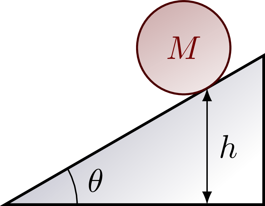
% INCLINED ground
\begin{tikzpicture}
\def\R{0.5} % disk radius
\def\W{3.2} % ground width
\def\ang{30} % ground angle
\def\mx{2.5} % mass x position
\coordinate (X) at (\ang:\mx); % wheel position
\coordinate (C) at ($(X)+(\ang+90:\R)$); % wheel center
\draw[thick,top color=blue!20!black!30,bottom color=white,shading angle=\ang+10]
(0,0) coordinate (O) -- (\ang:\W) coordinate (T) -- ({\W*cos(\ang)},0) coordinate (L) -- cycle;
\draw[mass] (C) circle(\R) node[myred!70!black] {$M$};
\draw pic["$\theta$",draw=black,angle radius=22,angle eccentricity=1.3] {angle=L--O--T};
\draw[<->] (X) --++ (0,{-\mx*sin(\ang)}) node[midway,right] {$h$};
\end{tikzpicture}
\end{document}
Click to download: dynamics_rolling.tex • dynamics_rolling.pdf
Open in Overleaf: dynamics_rolling.tex