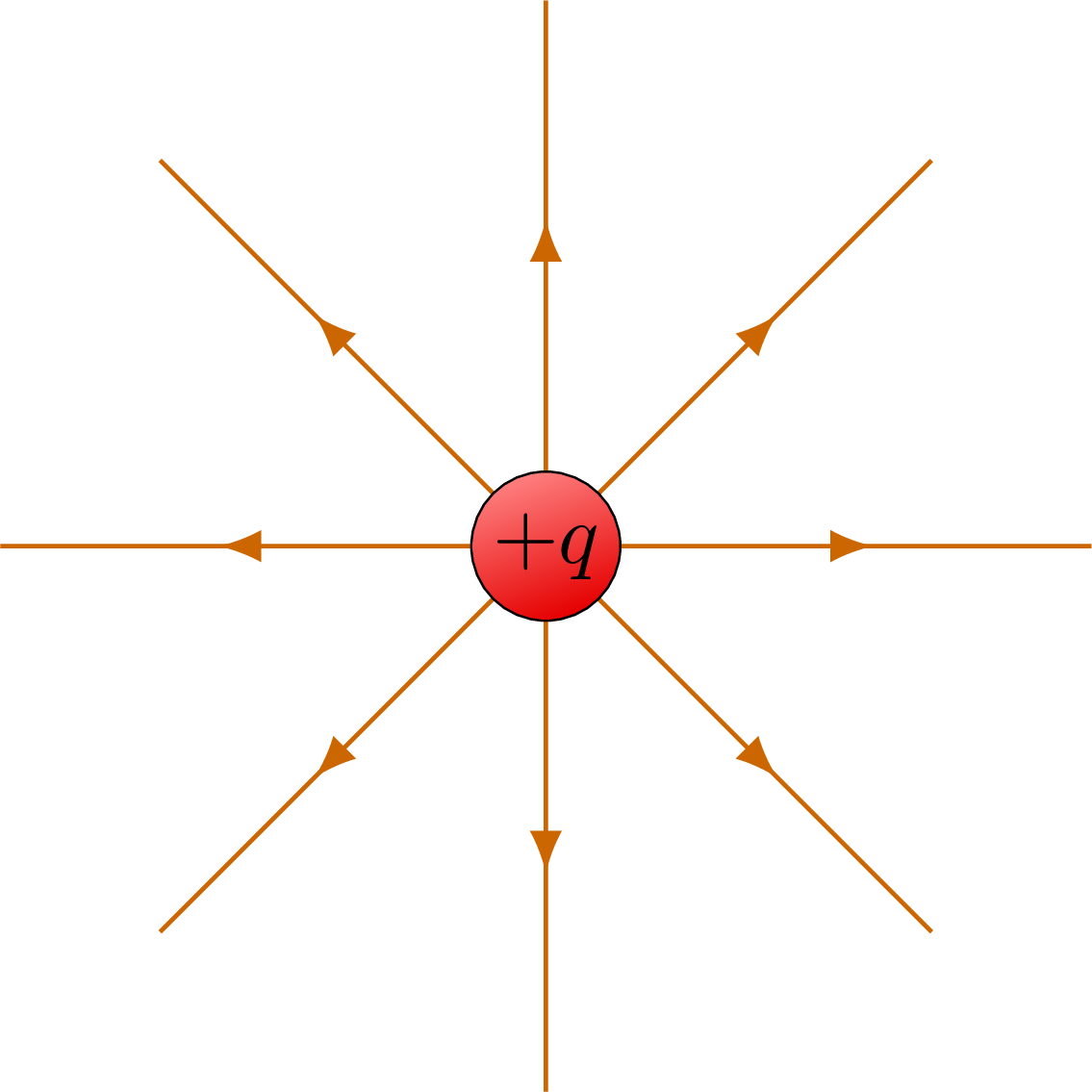
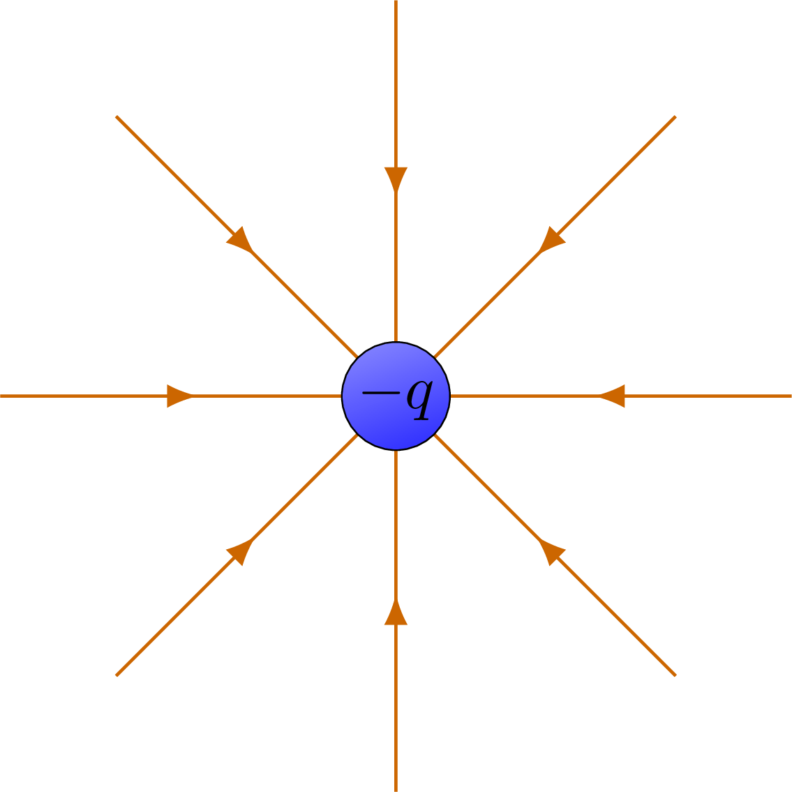
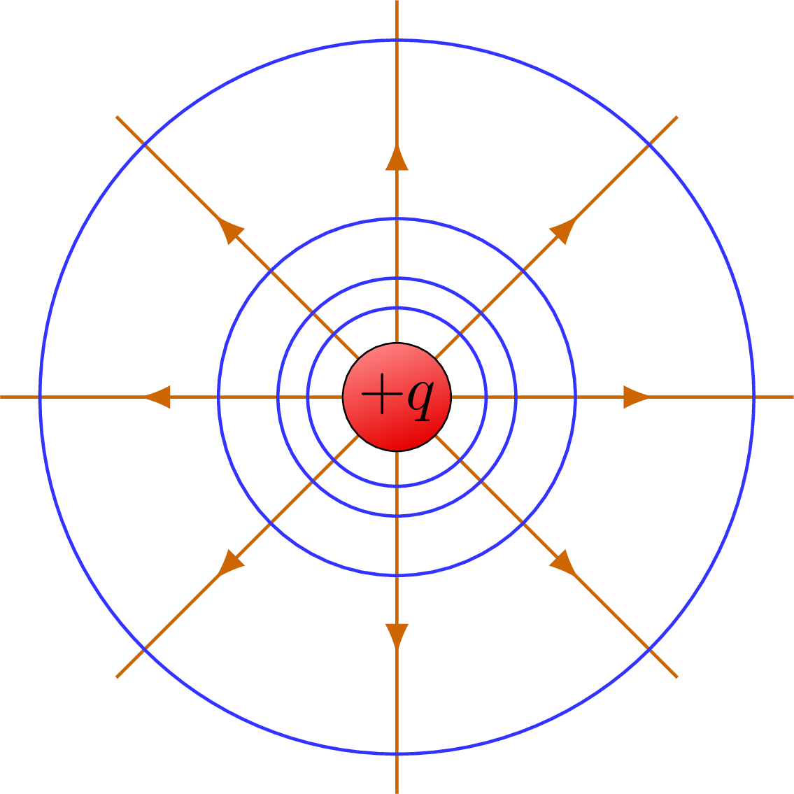
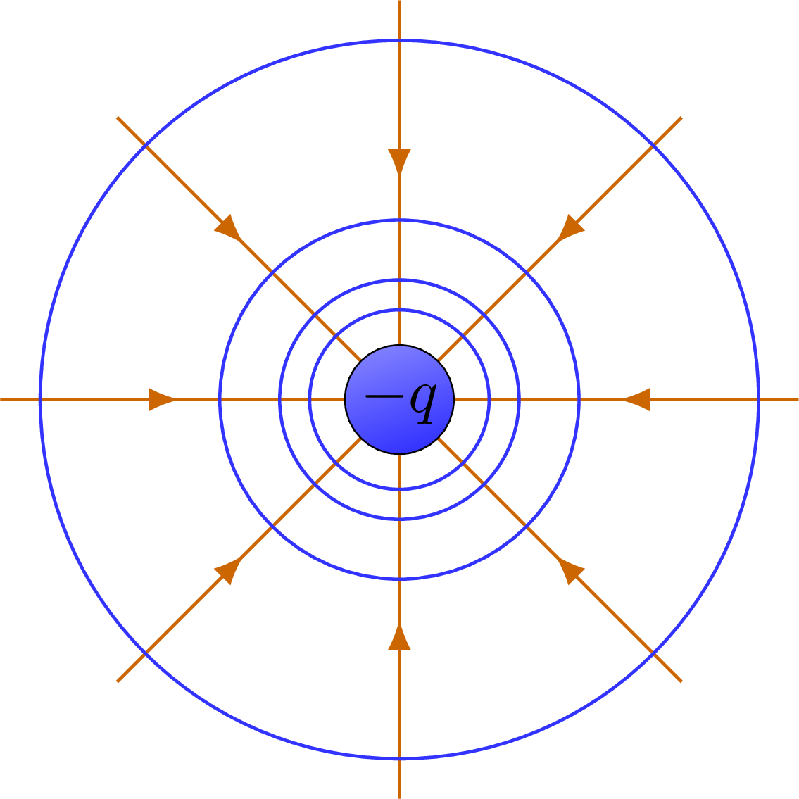
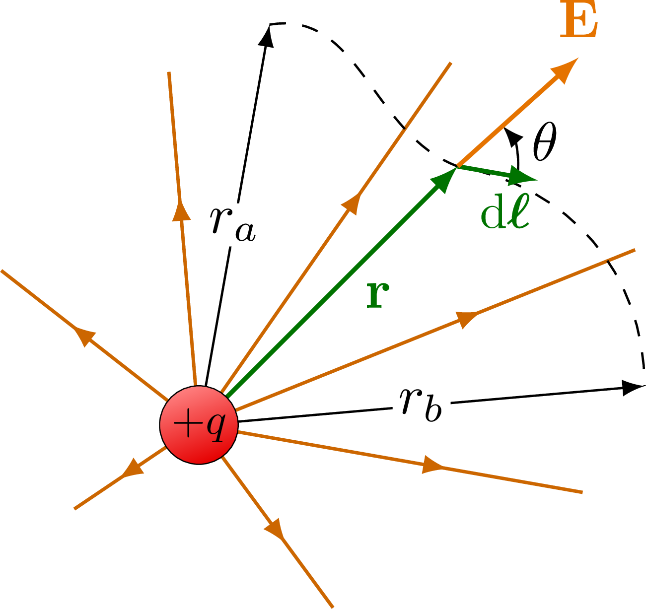
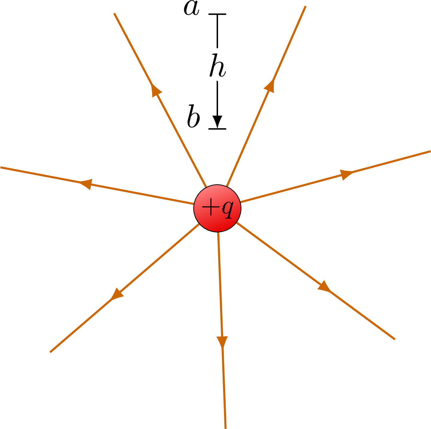
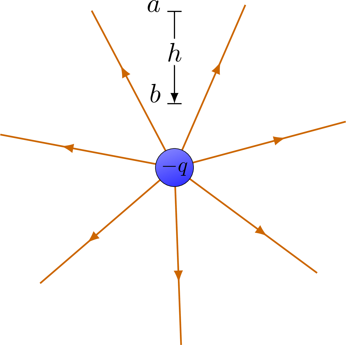
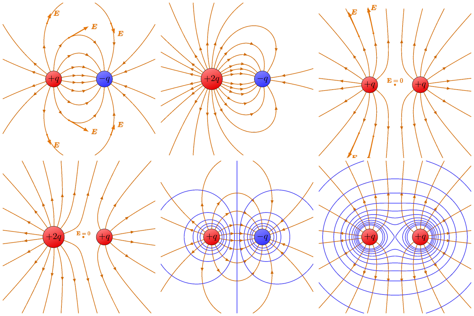
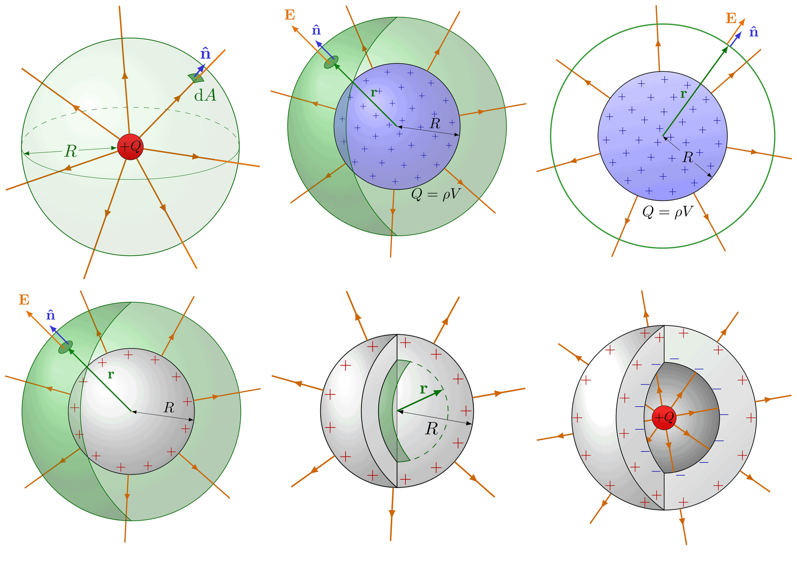
The electric field lines and equipotential surfaces of a point charge.
Edit and compile if you like:
% Author: Izaak Neutelings (July 2018)
% page 8 https://archive.org/details/StaticAndDynamicElectricity
% https://tex.stackexchange.com/questions/56353/extract-x-y-coordinate-of-an-arbitrary-point-on-curve-in-tikz
% https://tex.stackexchange.com/questions/412899/tikz-calculate-and-store-the-euclidian-distance-between-two-coordinates

\documentclass[border=3pt,tikz]{standalone}
\usepackage{physics,bm}
\usepackage{tikz,pgfplots}
\tikzset{>=latex} % for LaTeX arrow head
\pgfplotsset{compat=1.13}
\usetikzlibrary{decorations.markings,intersections,calc}
\usepackage[outline]{contour} % glow around text
\usetikzlibrary{angles,quotes} % for pic (angle labels)
\usepackage{xcolor}
\colorlet{Ecol}{orange!90!black}
\colorlet{EcolFL}{orange!80!black}
\colorlet{Bcol}{blue!90!black}
\tikzstyle{EcolEP}=[blue!80!white]
\colorlet{veccol}{green!45!black}
\tikzstyle{charge+}=[very thin,top color=red!50,bottom color=red!90!black,shading angle=20]
\tikzstyle{charge-}=[very thin,top color=blue!50,bottom color=blue!80,shading angle=20]
\tikzstyle{vector}=[->,thick,veccol]
\tikzset{EFieldLineArrow/.style={EcolFL,decoration={markings,mark=at position #1 with {\arrow{latex}}},
                                 postaction={decorate}},
         EFieldLineArrow/.default=0.5}
\def\R{1.8}
\def\NE{8}
\def\NV{4}
\contourlength{1.6pt}


\begin{document}


% POINT CHARGE +1
\begin{tikzpicture}
  \foreach \i [evaluate={\angle=(\i-1)*360/\NE;}] in {1,...,\NE}{
    \draw[EFieldLineArrow={0.6}] (0,0) -- (\angle:\R);
  }
  \draw[charge+] (0,0) circle (7pt) node[black,scale=0.8] {$+q$};
\end{tikzpicture}


% POINT CHARGE -1
\begin{tikzpicture}
  \foreach \i [evaluate={\angle=(\i-1)*360/\NE;}] in {1,...,\NE}{
    \draw[EFieldLineArrow={0.5}] (\angle:\R) -- (0:0);
  }
  \draw[charge-] (0,0) circle (7pt) node[black,scale=0.8] {$-q$};
\end{tikzpicture}


% POINT CHARGE +1 - equipotential
\begin{tikzpicture}
  \foreach \i [evaluate={\angle=(\i-1)*360/\NE;}] in {1,...,\NE}{
    \draw[EFieldLineArrow={0.65}] (0,0) -- (\angle:\R);
  }
  \foreach \i [evaluate={\r=0.9*\R/\i;}] in {1,...,\NV}{
    \draw[EcolEP] (0,0) circle (\r);
  }
  \draw[charge+] (0,0) circle (7pt) node[black,scale=0.8] {$+q$};
\end{tikzpicture}


% POINT CHARGE -1 - equipotential
\begin{tikzpicture}
  \foreach \i [evaluate={\angle=(\i-1)*360/\NE;}] in {1,...,\NE}{
    \draw[EFieldLineArrow={0.45}] (\angle:\R) -- (0,0);
  }
  \foreach \i [evaluate={\r=0.9*\R/\i;}] in {1,...,\NV}{
    \draw[EcolEP] (0,0) circle (\r);
  }
  \draw[charge-] (0,0) circle (7pt) node[black,scale=0.8] {$-q$};
\end{tikzpicture}


% POINT CHARGE +1 - integration
\begin{tikzpicture}[scale=1.3]
  \def\NE{7}
  \def\R{2.0}
  \def\a{1.6}
  \def\b{1.4}
  \coordinate (O) at (0,0);
  \coordinate (P) at (45:0.9*\R);
  \coordinate (L) at ($(P)+(-10:0.20*\R)$);
  \coordinate (E) at ($(P)+(42:0.4*\R)$);
  \foreach \i [evaluate={\ang=15+(\i-1)*360/\NE;}] in {1,...,\NE}{
    \draw[EFieldLineArrow={0.65},line width=0.6] (0,0) -- ({0.3*\R+\a*cos(\ang)},{0.25*\R+\b*sin(\ang)});
  }
  \draw[->] (O) -- (80:1.0*\R) coordinate (A) node[midway,fill=white,inner sep=1] {$r_a$};
  \draw[->] (O) -- (5:1.1*\R) coordinate (B) node[midway,fill=white,inner sep=1] {$r_b$};
  \draw[thin,dashed] (A) to[out=10,in=160] (P) to[out=-10,in=90] (B);
  \draw[vector] (O) -- (P) node[midway,right=9,below=-6] {$\vb{r}$};
  \draw pic[->,"$\theta$",draw=black,angle radius=11,angle eccentricity=1.5] {angle = L--P--E};
  \draw[vector] (P) -- (L) node[above=2,left=6,below=1,scale=0.9] {$\dd{\bm{\ell}}$};
  \draw[vector,Ecol] (P) -- (E) node[above] {$\vb{E}$};
  \draw[charge+] (O) circle (5.5pt) node[black,scale=0.8] {$+q$};
\end{tikzpicture}


% POINT CHARGE +1 - potential
\def\NE{7}
\def\a{0.04*\R}
\def\R{1.8}
\begin{tikzpicture}[scale=1.3]
  \foreach \i [evaluate={\angle=15+(\i-1)*360/\NE;}] in {1,...,\NE}{
    \draw[EFieldLineArrow={0.65},line width=0.6] (0,0) -- (\angle:\R);
  }
  \draw[charge+] (0,0) circle (5.5pt) node[black,scale=0.8] {$+q$};
  \draw[thin] (90:0.88*\R) coordinate (A) --++ (\a,0) --++ (-2*\a,0) node[above=2,left=-1] {$a$};
  \draw[thin] (90:0.36*\R) coordinate (B) --++ (\a,0) --++ (-2*\a,0) node[above=4,left=-1] {$b$};
  \draw[->] (A) -- (B) node[midway,above=-5] {\contour{white}{$h$}};
\end{tikzpicture}


% POINT CHARGE -1 - potential
\begin{tikzpicture}[scale=1.3]
  \foreach \i [evaluate={\angle=15+(\i-1)*360/\NE;}] in {1,...,\NE}{
    \draw[EFieldLineArrow={0.65},line width=0.6] (0,0) -- (\angle:\R);
  }
  \draw[charge-] (0,0) circle (5.5pt) node[black,scale=0.8] {$-q$};
  \draw[thin] (90:0.88*\R) coordinate (A) --++ (\a,0) --++ (-2*\a,0) node[above=2,left=-1] {$a$};
  \draw[thin] (90:0.36*\R) coordinate (B) --++ (\a,0) --++ (-2*\a,0) node[above=4,left=-1] {$b$};
  \draw[->] (A) -- (B) node[midway,above=-5] {\contour{white}{$h$}};
\end{tikzpicture}


\end{document}
Click to download: electric_fieldlines1.tex • electric_fieldlines1.pdf
Open in Overleaf: electric_fieldlines1.tex


Hi!
I was wondering how I could turn this diagram into a simple accretion disc model to represent formation of stars and planets in the early solar system (for igcse 0625)…. I was thinking that it could be done somehow, I am just not sure how… could you point me in the right direction?
Again, thank you so much for making all of your diagrams available! I really appreciate it! 🙂
Hi Wagner, thanks!
I guess you could do something like this, where you use
even odd ruleto fill between two ellipses, and you have to draw first on the back, then again on the front, clipping the bottom part:% Author: Izaak Neutelings (July 2018) \documentclass[border=3pt,tikz]{standalone} \usepackage{physics,bm} \usepackage{tikz,pgfplots} \tikzset{>=latex} % for LaTeX arrow head \pgfplotsset{compat=1.13} \usetikzlibrary{decorations.markings,intersections,calc} \usepackage[outline]{contour} % glow around text \usetikzlibrary{angles,quotes} % for pic (angle labels) \usepackage{xcolor} \colorlet{Ecol}{orange!90!black} \colorlet{EcolFL}{orange!80!black} \colorlet{Bcol}{blue!90!black} \tikzstyle{EcolEP}=[blue!80!white] \colorlet{veccol}{green!45!black} \tikzstyle{charge+}=[very thin,top color=red!50,bottom color=red!90!black,shading angle=20] \tikzstyle{charge-}=[very thin,top color=blue!50,bottom color=blue!80,shading angle=20] \tikzstyle{vector}=[->,thick,veccol] \tikzset{EFieldLineArrow/.style={EcolFL,decoration={markings,mark=at position #1 with {\arrow{latex}}}, postaction={decorate}}, EFieldLineArrow/.default=0.5} \def\R{1.8} \def\NE{8} \def\NV{4} \contourlength{1.6pt} \begin{document} \begin{tikzpicture} \def\rinx{12pt} \def\riny{4pt} \def\routx{25pt} \def\routy{12pt} \def\drawdisk{ \fill[top color=blue!50!black!20,bottom color=blue!60!black!8, shading angle=30,even odd rule] (0,0) ellipse({\rinx} and {\riny}) (0,0) ellipse({\routx} and {\routy}); } \drawdisk % draw back \foreach \i [evaluate={\angle=(\i-1)*360/\NE;}] in {1,...,\NE}{ \draw[EFieldLineArrow={0.6}] (0,0) -- (\angle:\R); } \draw[charge+] (0,0) circle(7pt) node[black,scale=0.8] {$+q$}; \clip (-\routx,-\routy) rectangle (\routx,-0.03); \drawdisk % draw front (clipped bottom part) \end{tikzpicture} \end{document}Wow! Thank you so much!
I will have a go and whatever I am able to expand on this, I will share with you! 🙂
Again, thank you!
Wow! Thank you so much!
I will have a go and whatever I am able to expand on this, I will share with you! 🙂