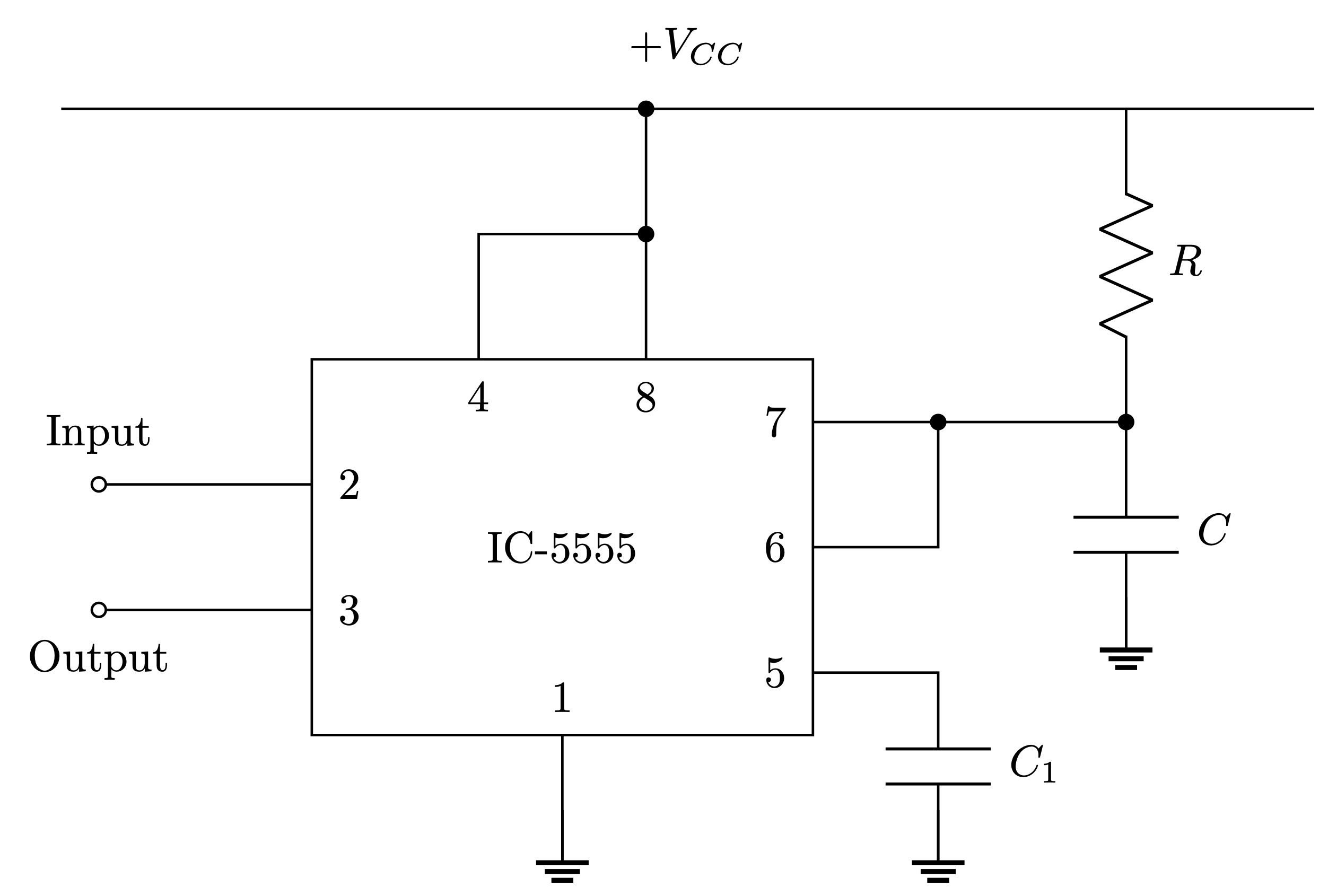
Monostable Multivibrator
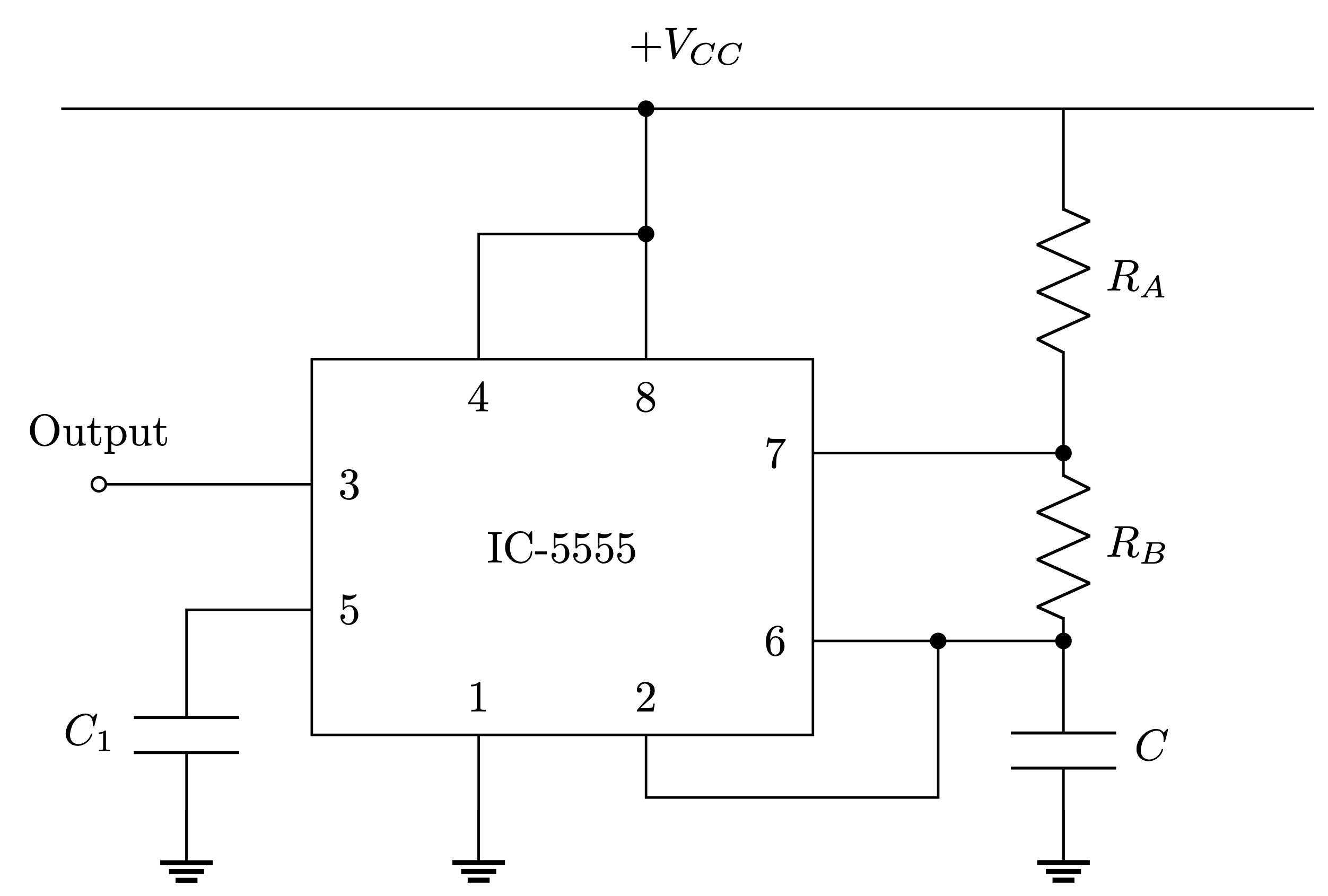
Multistable Multivibrator
Code
\documentclass[border=3pt, tikz]{standalone}

% Circuits
\usepackage[european,s traightvoltages, RPvoltages, americanresistor, americaninductors]{circuitikz}
\tikzset{every picture/.style={line width=0.2mm}}

% Tikz Library
\usetikzlibrary{calc}

% Bipoles Specifications
\ctikzset{bipoles/thickness=1.2, label distance=1mm, voltage shift = 1}

\def\nu{10}
\def\nodesep{0.3}

\begin{document}

	\begin{tikzpicture}
	\begin{circuitikz}
%		% Grid
%		\draw[thin, dotted] (0,0) grid (\nu,\nu);
%		\foreach \i in {1,...,\nu}
%		{
%			\node at (\i,-2ex) {\i};
%		}
%		\foreach \i in {1,...,\nu}
%		{
%			\node at (-2ex,\i) {\i};
%		}
%		\node at (-2ex,-2ex) {0};

		% Coordinates
		\coordinate (DC left) at (0,6);
		\coordinate (DC right) at (10,6);
		%% IC
		\coordinate (left bottom corner) at (2,1);
		\coordinate (right top corner) at (6,4);
		\coordinate (left top corner) at (left bottom corner |- right top corner);
		\coordinate (right bottom corner) at (left bottom corner -| right top corner);
		\coordinate (middle left) at ($(left bottom corner)!0.5!(left top corner)$);
		\coordinate (middle right) at ($(right bottom corner)!0.5!(right top corner)$);
		%% IC Nodes
		\coordinate (1) at ($(left bottom corner)!0.5!(right bottom corner)$);
		\coordinate (2) at ($(left top corner)!0.333!(left bottom corner)$);
		\coordinate (3) at ($(left top corner)!0.667!(left bottom corner)$);
		\coordinate (4) at ($(left top corner)!0.333!(right top corner)$);
		\coordinate (5) at ($(right bottom corner)!0.166!(right top corner)$);
		\coordinate (6) at ($(right bottom corner)!0.50!(right top corner)$);
		\coordinate (7) at ($(right bottom corner)!0.833!(right top corner)$);
		\coordinate (8) at ($(left top corner)!0.667!(right top corner)$);

		% Circuit
		\draw

		(DC left) -- (DC right)

		(left bottom corner) rectangle (right top corner)

		(1) -- ++(0,-1) node[ground, shift={(0,0.4)}] {}

		(2) to[short, -o] ++(-1.7,0) node[shift={(0,0.4)}] {Input}

		(3) to[short, -o] ++(-1.7,0) node[shift={(0,-0.4)}] {Output}

		(4) -- ++(0,1) coordinate(4') to[short, -*] (8 |- 4')

		(5) -- ++(1,0) coordinate(5') to[C, l^=$C_1$] (5' |- 0,0) node[ground, shift={(0,0.4)}] {}

		(6) -- ++(1,0) coordinate(6') to[short, -*] (7 -| 6')

		(7) to[short, -*] ++(2.5,0) coordinate(7') to[C, l^=$C$] ++(0,-1.8) node[ground, shift={(0,0.4)}] {}
		(7') to[R, l_=$R$] (7' |- DC right)

		(8) to[short, -*] (8 |- DC right);

		% Nodes
		%% IC
		\node[shift={(0,\nodesep)}] at (1) {$1$};
		\node[shift={(\nodesep,0)}] at (2) {$2$};
		\node[shift={(\nodesep,0)}] at (3) {$3$};
		\node[shift={(0,-\nodesep)}] at (4) {$4$};
		\node[shift={(-\nodesep,0)}] at (5) {$5$};
		\node[shift={(-\nodesep,0)}] at (6) {$6$};
		\node[shift={(-\nodesep,0)}] at (7) {$7$};
		\node[shift={(0,-\nodesep)}] at (8) {$8$};
		%% Other
		\node at ($(middle left)!0.5!(middle right)$) {IC-5555};
		\node[shift={(0,0.5)}] at ($(DC left)!0.5!(DC right)$) {$+V_{CC}$};

	\end{circuitikz}
	\end{tikzpicture}

\def\nu{10}
\def\nodesep{0.3}

	\begin{tikzpicture}
	\begin{circuitikz}
%		% Grid
%		\draw[thin, dotted] (0,0) grid (\nu,\nu);
%		\foreach \i in {1,...,\nu}
%		{
%			\node at (\i,-2ex) {\i};
%		}
%		\foreach \i in {1,...,\nu}
%		{
%			\node at (-2ex,\i) {\i};
%		}
%		\node at (-2ex,-2ex) {0};

		% Coordinates
		\coordinate (DC left) at (0,6);
		\coordinate (DC right) at (10,6);
		%% IC
		\coordinate (left bottom corner) at (2,1);
		\coordinate (right top corner) at (6,4);
		\coordinate (left top corner) at (left bottom corner |- right top corner);
		\coordinate (right bottom corner) at (left bottom corner -| right top corner);
		\coordinate (middle left) at ($(left bottom corner)!0.5!(left top corner)$);
		\coordinate (middle right) at ($(right bottom corner)!0.5!(right top corner)$);
		%% IC Nodes
		\coordinate (1) at ($(left bottom corner)!0.333!(right bottom corner)$);
		\coordinate (2) at ($(left bottom corner)!0.667!(right bottom corner)$);
		\coordinate (3) at ($(left top corner)!0.333!(left bottom corner)$);
		\coordinate (4) at ($(left top corner)!0.333!(right top corner)$);
		\coordinate (5) at ($(left top corner)!0.667!(left bottom corner)$);
		\coordinate (6) at ($(right bottom corner)!0.25!(right top corner)$);
		\coordinate (7) at ($(right bottom corner)!0.75!(right top corner)$);
		\coordinate (8) at ($(left top corner)!0.667!(right top corner)$);

		% Circuit
		\draw

		(DC left) -- (DC right)

		(left bottom corner) rectangle (right top corner)

		(1) -- ++(0,-1) node[ground, shift={(0,0.4)}] {}

		(2) -- ++(0,-0.5) coordinate(2') -- (6 |- 2') -- ++(1,0) coordinate(2'') to[short, -*] (2'' |- 6)

		(3) to[short, -o] ++(-1.7,0) node[shift={(0,0.4)}] {Output}

		(4) -- ++(0,1) coordinate(4') to[short, -*] (8 |- 4')

		(5) -- ++(-1,0) to[C, l_=$C_1$] ++(0,-2) node[ground, shift={(0,0.4)}] {}

		(6) to[short, -*] ++(2,0) coordinate(6') to[C, l^=$C$] (6' |- 0,0) node[ground, shift={(0,0.4)}] {}

		(7) to[short, -*] (7 -| 6') coordinate(7') to[R, l^=$R_B$] (6')
		(7') to[R, l_=$R_A$] (7' |- DC right)


		(8) to[short, -*] (8 |- DC right);

		% Nodes
		%% IC
		\node[shift={(0,\nodesep)}] at (1) {$1$};
		\node[shift={(0,\nodesep)}] at (2) {$2$};
		\node[shift={(\nodesep,0)}] at (3) {$3$};
		\node[shift={(0,-\nodesep)}] at (4) {$4$};
		\node[shift={(\nodesep,0)}] at (5) {$5$};
		\node[shift={(-\nodesep,0)}] at (6) {$6$};
		\node[shift={(-\nodesep,0)}] at (7) {$7$};
		\node[shift={(0,-\nodesep)}] at (8) {$8$};
		%% Other
		\node at ($(middle left)!0.5!(middle right)$) {IC-5555};
		\node[shift={(0,0.5)}] at ($(DC left)!0.5!(DC right)$) {$+V_{CC}$};

	\end{circuitikz}
	\end{tikzpicture}
\end{document}
")

