Edit and compile if you like:
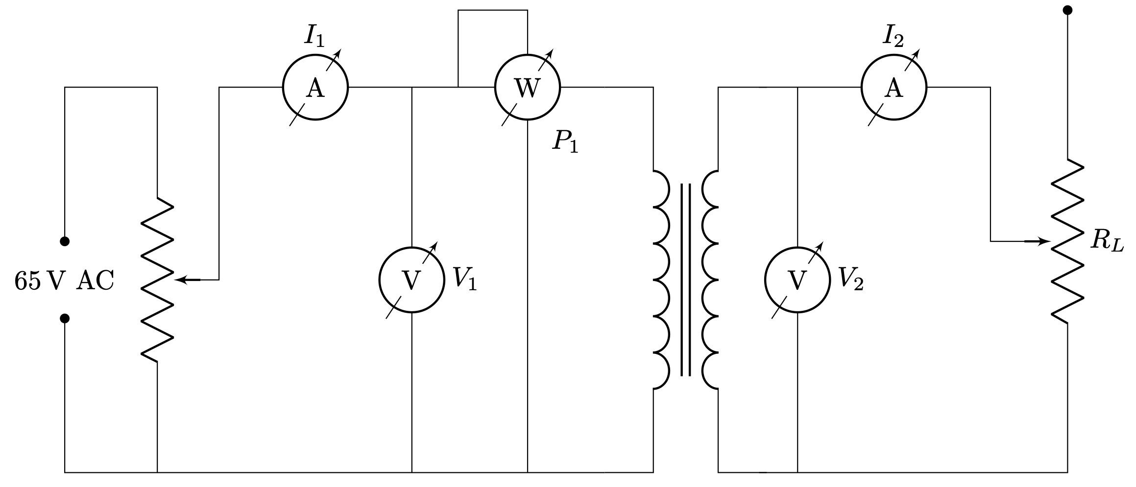
\documentclass[border=2pt]{standalone}% Circuit\usepackage{circuitikz}% Notation\usepackage{siunitx}\begin{document}\begin{circuitikz}% Specifications%% Resistors\ctikzset{resistors/zigs=5, resistors/width=1.5}%% Inductors\ctikzset{inductors/coils=6, quadpoles/transformer core/height=3.571, inductors/width=2}% Grid% \draw[help lines] (0,0) grid (14,13);%% \foreach \x in {0,1,2,3,...,13}% {% \node at (\x,-0.5) {\x};% \node at (-0.5, \x) {\x};% }% Nodes\node at (0,2.5) {\SI{65}{V} AC};\node at (6.5,4.3) {$P_1$};% Circuit%% Left Part\draw (7,0) -- (0,0) to[short, -*] +(0,2);\draw (0,3) to[short, *-] +(0,2) -- (1.2,5) to[pR, wiper pos=0.5, name=A] (1.2,0);\draw (A.wiper) -- (2,2.5) -- (2,5) to[rmeterwa, t=\si{A}, l=$I_1$] (4.5,5) -- +(0.5,0) to [rmeterwa, t=\si{W}] (7,5)node[american, transformer core, anchor=A1] (T) {}(T.A1) node {}(T.A2) node {}(T.B1) node {}
Click to download: transformer-circuit.tex
Open in Overleaf: transformer-circuit.tex
This file is available on GitHub.
See more on the author page of Alexandros Tsagkaropolulos.


