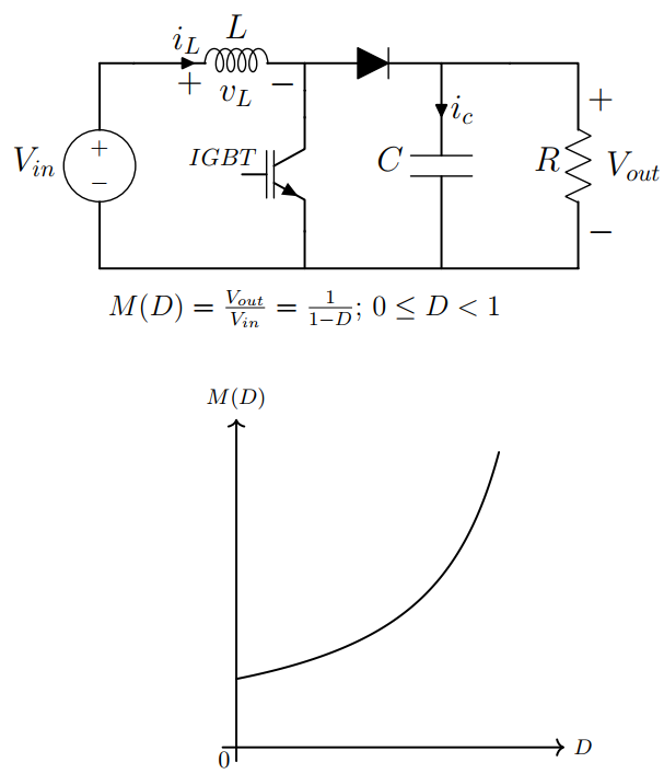
% Boost Converter
% This DC-DC converter increases the voltage level from input to output

% Designed by: Amir Ostadrahimi

\documentclass [border=5pt]{standalone}
\usepackage{tikz}
\usepackage[american,cuteinductors,smartlabels]{circuitikz} % A package to draw electrical networks with TikZ

%-- the dimensions of the elements can be changed here
\ctikzset{bipoles/thickness=0.7}
\ctikzset{bipoles/length=1.5cm}
\ctikzset{bipoles/resistor/width=.7}
\ctikzset{bipoles/resistor/height=.25}
\ctikzset{bipoles/diode/height=.3}
\ctikzset{bipoles/diode/width=.3}
\ctikzset{tripoles/thickness=.7}
\ctikzset{bipoles/vsourceam/height/.initial=.7}
\ctikzset{bipoles/vsourceam/width/.initial=.7}
\ctikzset{bipoles/vsourceam/width/.initial=.7}

%settings for fonts and lines
\tikzstyle{every node}=[font=\Large]
\tikzstyle{every path}=[line width=0.9 pt, line cap=round, line join=round]


\begin{document}

 \begin{circuitikz}

%------ Converter
\coordinate  (VBottom) at (0,0); %%VBottom stands for voltage source bottom and is located on (0,0)

\draw (VBottom) to [V, l=$V_{in}$, invert] ++(0,3) coordinate (VTop); % "V" is to insert voltage source, instead of "V", you can use "battery", "battery1", and "battery2".
% the " l=$V_{in}$" is for label. You can use  "l_=$V_{in}$" or "l^=$V_{in}$" to change its location.
%"invert" changes the polarity of the source. (VTop) stands for voltage top.

\draw (VTop) to [short] ++(1,0) to [L, l=$L$, v=$v_L$, i>^=$i_L$]++ (2,0) coordinate (InductorRight);  % "i>^=$i_L$ " is for showing the current of the element, by using "^" we can change its location and bring it at the input and the output of the element. By using  "<"  and  ">"  we can change its direction. And finally by using "_" we can change its vertical location.

\draw (InductorRight) to [short]++(0,-0.8) node [nigbt, anchor=C, label={ [xshift=-1.2cm, yshift=0] \normalsize $IGBT$}] (nigbt1){}; % here we used an N-channel IGBT using "nigbt". Alternatively, we could use "pigbt", "nmos", "pmos" and so on.

\draw (nigbt1.E)-- (nigbt1.E |-VBottom); % using this command, a line starts from the Emitter of the IGBT and extends vertically until reaches the intersection of the vertical line from (nigbt1.E) and the horizontal line from (VB).

\draw (InductorRight) to [D*] ++(2,0) coordinate (DiodeRight) to [C, l_=$C$, i>^=$i_c$](DiodeRight|-VBottom); % using [D*] makes the diode solid black. If we just use [D], the diode will be white.

\draw
(DiodeRight) to [short]++(2,0) coordinate(ResistorTop) to [R, l_=$R$, v^=$V_{out}$](ResistorTop|-VBottom) coordinate (ResistorBottom)

(ResistorBottom)-- (VBottom);

%------ Conversion Ratio

\coordinate [label={ [xshift=0, yshift=0] \large $ M(D)=\frac{V_{out}}{V_{in}}=\frac{1}{1-D};$ \large $0 \leq D < 1$ }] (M) at (3,-1);

%------ Curve

\def\xo{2} % Axes of origin
\def\yo{-7} % Axes of origin
\def\length {5} % length of the axes
\def\N{200} %number of samples

\coordinate [label={ [xshift=-5, yshift=-12]  \normalsize$0$ }] (origin) at (\xo,\yo); %

\draw[->] (\xo -0.2, \yo) --++(\length,0) node[right] {\small $D$};
 \draw[->]  (\xo,\yo -0.2) -- ++(0, \length) node[above] {\small $M(D)$};
\draw     plot[samples=\N, domain=  0     :   0.77, xshift=\xo cm, yshift=\yo cm] (5*\x  ,{1/(1-\x)});


\end{circuitikz}


\end{document}
4 Replies to “Boost Converter”
Please fix the maximum point to 0.77 so the graph will be in the frame of axis. The circuit is fantastic
")


Please fix the maximum point to 0.77 so the graph will be in the frame of axis. The circuit is fantastic
Thanks. The change was applied.
Also If you want to begin the graph from zero you should decrease the yshift to -8cm
It is a boost converter, and logically it should start from 1, so “-7” is correct.