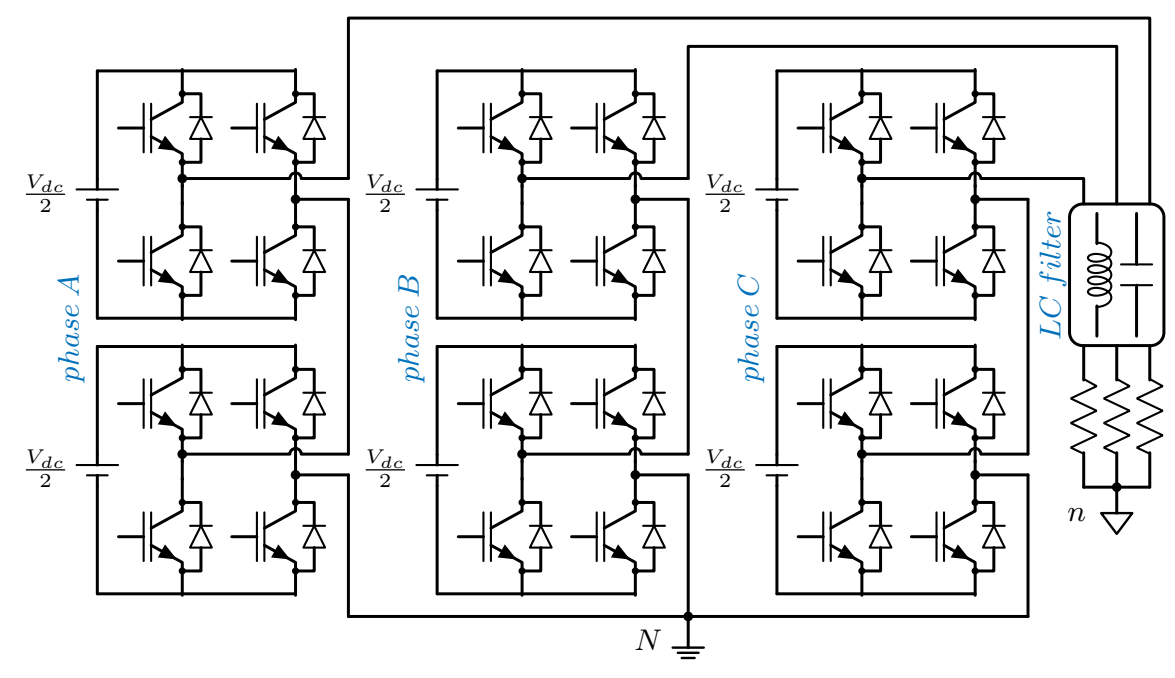
% Three phase 5-Level Cascaded H-Bridge Converter (CHB)
% Author: Amir Ostadrahimi
\documentclass [border=5pt]{standalone}
\usepackage{tikz}
\usepackage[american,cuteinductors,smartlabels]{circuitikz} % A package to draw electrical networks with TikZ

%-- the dimensions of the elements can be changed here
\ctikzset{bipoles/thickness=0.7}
\ctikzset{grounds/thickness=0.8}
\ctikzset{bipoles/length=1.1cm}
\ctikzset{bipoles/resistor/width=.7}
\ctikzset{bipoles/resistor/height=.25}
\ctikzset{bipoles/diode/height=.7}
\ctikzset{bipoles/diode/width=.7}
\ctikzset{tripoles/thickness=.7}
\ctikzset{bipoles/vsourceam/height/.initial=.7}
\ctikzset{bipoles/vsourceam/width/.initial=.7}
\ctikzset{bipoles/battery1/height=.4}
\ctikzset{bipoles/vsourceam/width/.initial=.7}

\tikzstyle{every node}=[font=\small]
\tikzstyle{every path}=[line width=0.9 pt, line cap=round, line join=round]


% difining new colors
\definecolor{MatlabBlue}{rgb}{0 0.4470 0.7410} % define the blue color of the Matlab
%

% defining distances between elements--- One can change the dimension fo the converter by changing these distances:
\newcommand\IHD{1.2} %Horizontal distance between IGBTs in a cell
\newcommand\IVD{0.2} %Vertical distance between IGBTs in a cell
\newcommand\VSD{0.9} %distance of the voltage source
\newcommand\VCD{0.3} %Vertical Cell Distance between cells
\newcommand\GL{1.5} %GL means ground connection length
\newcommand\HPD{3.6} %HPD stands for Horizontal Phase distance
\newcommand\fillsize{1} %fillsize


\begin{document}

 \begin{circuitikz}

%---- Phase A, Bottom cell
\coordinate  (AB) at (0,0); %%AB stands for phase A, Bottom
\draw (AB) node[nigbt, bodydiode, anchor=E](B4A){} --++(-\IHD,0) node[nigbt, bodydiode, anchor=E](B2A){} ; % using "node" we defined IGBT with diode
\draw  (B2A.C) --++(0,\IVD) node[nigbt, bodydiode, anchor=E](B1A){} ; %% B1A stands for Bottom 1st phase A
\draw  (B4A.C) --++(0,\IVD) node[nigbt, bodydiode, anchor=E](B3A){} ;
\draw  (B3A.C) --(B1A.C){} ;

%---   Connections with other cell
\draw  (B1A.C)--++(-\VSD,0)  coordinate (ABVP); %% ABVP stands for phase A, bottom cell, positive pole
\draw (B2A.E)--++(-\VSD,0)  coordinate (ABVN); %% ABVN stands for phase A, bottom cell, negative pole
\draw (ABVP) to [battery1,  l_=$\frac {V_{dc}}{2}$] (ABVN);

%---
\draw  (B2A.C)++ (0,0.27) coordinate  (Con1AB) ; %% Con1AB stands for connection 1 phase A, Bottom
\filldraw  (Con1AB) circle (\fillsize pt);

\draw  (B4A.C)++ (0,0.05) coordinate  (Con2AB) ; %% Con1AB stands for connection 2 phase A, Bottom
\filldraw  (Con2AB) circle (\fillsize pt);

\draw (Con1AB) --++ (\IHD-0.06,0)  arc (180:0:0.06) -- ++(0.5,0) coordinate (ABOP); %ABOP stands for phase A, Bottom cell, Output, Positive
\draw (Con2AB) -- ++(0.56,0)  coordinate (ABON); %ABOP stands for phase A, Bottom cell, Output, Negative


%---- Phase A, Top cell
\draw (B3A.C)++  (0,\VCD) coordinate (AT); %% AT means phase A, Top
\draw (AT) node[nigbt, bodydiode, anchor=E](T4A){} --++(-\IHD,0) node[nigbt, bodydiode, anchor=E](T2A){} ;
\draw  (T2A.C) --++(0,\IVD) node[nigbt, bodydiode, anchor=E](T1A){} ; %% T1A stands for Top 1st phase A
\draw  (T4A.C) --++(0,\IVD) node[nigbt, bodydiode, anchor=E](T3A){} ;
\draw  (T3A.C) --(T1A.C){} ;

%---   Connections with other cell
\draw  (T1A.C)--++(-\VSD,0)  coordinate (ATVP); %% ATVP stands for phase A, Top cell, positive pole
\draw (T2A.E)--++(-\VSD,0)  coordinate (ATVN); %% ABVN stands for phase A, Top cell, negative pole
\draw (ATVP) to [battery1,  l_=$\frac {V_{dc}}{2}$] (ATVN);
%---
\draw  (T2A.C)++ (0,0.27) coordinate  (Con1AT) ; %% Con1AB stands for connection 1 phase A, ToP
\filldraw  (Con1AT) circle (\fillsize pt);

\draw  (T4A.C)++ (0,0.05) coordinate  (Con2AT) ; %% Con1AB stands for connection 2 phase A, Top
\filldraw  (Con2AT) circle (\fillsize pt);

\draw (Con1AT) --++ (\IHD-0.06,0)  arc (180:0:0.06) -- ++(0.5,0) coordinate (ATOP); %ATOP stands for phase A, Top cell, Output, Positive
\draw (Con2AT) -- ++(0.56,0)  coordinate (ATON); %ATOP stands for phase A, Top cell, Output, Negative

%--- Intra-cell connections
\draw (ATON) -- (ABOP);
\draw (ABON) --++(0,-\GL) coordinate (AG); % AG stands for ground connection of phase A


%%---- PHASE NAME
\draw (ABVP)++  (0,0.2) coordinate (A-NAME);
\coordinate [label={[MatlabBlue, xshift=0, yshift=0, rotate=90]  $phase\: A$ }] (A-NAME) at (A-NAME);


%------- Phase B, Bottom cell
\draw (AB)++  (\HPD, 0) coordinate (BB); %%BB stands for phase B, Bottom

\draw (BB) node[nigbt, bodydiode, anchor=E](B4B){} --++(-\IHD,0) node[nigbt, bodydiode, anchor=E](B2B){} ;
\draw  (B2B.C) --++(0,\IVD) node[nigbt, bodydiode, anchor=E](B1B){} ; %% B1B stands for Bottom 1st phase B
\draw  (B4B.C) --++(0,\IVD) node[nigbt, bodydiode, anchor=E](B3B){} ;
\draw  (B3B.C) --(B1B.C){} ;


%---   Connections with other cell
\draw  (B1B.C)--++(-\VSD,0)  coordinate (BBVP); %% BBVP stands for phase B, bottom cell, positive pole
\draw (B2B.E)--++(-\VSD,0)  coordinate (BBVN); %% BBVN stands for phase B, bottom cell, negative pole
\draw (BBVP) to [battery1,  l_=$\frac {V_{dc}}{2}$] (BBVN);
%---
\draw  (B2B.C)++ (0,0.27) coordinate  (Con1BB) ; %% Con1BB stands for connection 1 phase B, Bottom
\filldraw  (Con1BB) circle (\fillsize pt);

\draw  (B4B.C)++ (0,0.05) coordinate  (Con2BB) ; %% Con1BB stands for connection 2 phase B, Bottom
\filldraw  (Con2BB) circle (\fillsize pt);

\draw (Con1BB) --++ (\IHD-0.06,0)  arc (180:0:0.06) -- ++(0.5,0) coordinate (BBOP); %BBOP stands for phase B, Bottom cell, Output, Positive
\draw (Con2BB) -- ++(0.56,0)  coordinate (BBON); %BBOP stands for phase B, Bottom cell, Output, Negative


%---- Phase B, Top cell
\draw (B3B.C)++  (0,\VCD) coordinate (BT); %% BT means phase B, Top

\draw (BT) node[nigbt, bodydiode, anchor=E](T4B){} --++(-\IHD,0) node[nigbt, bodydiode, anchor=E](T2B){} ;
\draw  (T2B.C) --++(0,\IVD) node[nigbt, bodydiode, anchor=E](T1B){} ; %% T1B stands for Top 1st phase B
\draw  (T4B.C) --++(0,\IVD) node[nigbt, bodydiode, anchor=E](T3B){} ;
\draw  (T3B.C) --(T1B.C){} ;

%---   Connections with other cell
\draw  (T1B.C)--++(-\VSD,0)  coordinate (BTVP); %% ATVP stands for phase B, Top cell, positive pole
\draw (T2B.E)--++(-\VSD,0)  coordinate (BTVN); %% ABVN stands for phase B, Top cell, negative pole
\draw (BTVP) to [battery1,  l_=$\frac {V_{dc}}{2}$] (BTVN);
%---
\draw  (T2B.C)++ (0,0.27) coordinate  (Con1BT) ; %% Con1BB stands for connection 1 phase B, ToP
\filldraw  (Con1BT) circle (\fillsize pt);

\draw  (T4B.C)++ (0,0.05) coordinate  (Con2BT) ; %% Con1AB stands for connection 2 phase B, Top
\filldraw  (Con2BT) circle (\fillsize pt);

\draw (Con1BT) --++ (\IHD-0.06,0)  arc (180:0:0.06) -- ++(0.5,0) coordinate (BTOP); %BTOP stands for phase B, Top cell, Output, Positive
\draw (Con2BT) -- ++(0.56,0)  coordinate (BTON); %BTOP stands for phase B, Top cell, Output, Negative


%--- Intra-cell connections
\draw (BTON) -- (BBOP);
\draw (BBON) --++(0,-\GL) coordinate (BG); % BG stands for ground connection of phase B


%%---- PHASE NAME
\draw (BBVP)++  (0,0.2) coordinate (B-NAME);
\coordinate [label={[MatlabBlue, xshift=0, yshift=0, rotate=90]  $phase\: B$ }] (B-NAME) at (B-NAME);


%---- Phase C, Bottom cell
\draw (BB)++  (\HPD, 0) coordinate (CB); %%CB stands for phase C, Bottom
\draw (CB) node[nigbt, bodydiode, anchor=E](B4C){} --++(-\IHD,0) node[nigbt, bodydiode, anchor=E](B2C){} ;
\draw  (B2C.C) --++(0,\IVD) node[nigbt, bodydiode, anchor=E](B1C){} ; %% B1C stands for Bottom 1st phase C
\draw  (B4C.C) --++(0,\IVD) node[nigbt, bodydiode, anchor=E](B3C){} ;
\draw  (B3C.C) --(B1C.C){} ;


%---   Connections with other cell
\draw  (B1C.C)--++(-\VSD,0)  coordinate (CBVP); %% CBVP stands for phase C, bottom cell, positive pole
\draw (B2C.E)--++(-\VSD,0)  coordinate (CBVN); %% CBVN stands for phase C, bottom cell, the negative pole
\draw (CBVP) to [battery1,  l_=$\frac {V_{dc}}{2}$] (CBVN);
%---
\draw  (B2C.C)++ (0,0.27) coordinate  (Con1CB) ; %% Con1CB stands for connection 1 phase C, Bottom
\filldraw  (Con1CB) circle (\fillsize pt);

\draw  (B4C.C)++ (0,0.05) coordinate  (Con2CB) ; %% Con1CB stands for connection 2 phase C, Bottom
\filldraw  (Con2CB) circle (\fillsize pt);

\draw (Con1CB) --++ (\IHD-0.06,0)  arc (180:0:0.06) -- ++(0.5,0) coordinate (CBOP); %CBOP stands for phase C, Bottom cell, Output, Positive
\draw (Con2CB) -- ++(0.56,0)  coordinate (CBON); %CBOP stands for phase C, Bottom cell, Output, Negative


%---- Phase C, Top cell
\draw (B3C.C)++  (0,\VCD) coordinate (CT); %% CT means phase C, Top
\draw (CT) node[nigbt, bodydiode, anchor=E](T4C){} --++(-\IHD,0) node[nigbt, bodydiode, anchor=E](T2C){} ;
\draw  (T2C.C) --++(0,\IVD) node[nigbt, bodydiode, anchor=E](T1C){} ; %% T1C stands for Top 1st phase C
\draw  (T4C.C) --++(0,\IVD) node[nigbt, bodydiode, anchor=E](T3C){} ;
\draw  (T3C.C) --(T1C.C){} ;

%---   Connections with other cell
\draw  (T1C.C)--++(-\VSD,0)  coordinate (CTVP); %% CTVP stands for phase C, Top cell, positive pole
\draw (T2C.E)--++(-\VSD,0)  coordinate (CTVN); %% CBVN stands for phase C, Top cell, negative pole
\draw (CTVP) to [battery1,  l_=$\frac {V_{dc}}{2}$] (CTVN);
%---
\draw  (T2C.C)++ (0,0.27) coordinate  (Con1CT) ; %% Con1CB stands for connection 1 phase C, ToP
\filldraw  (Con1CT) circle (\fillsize pt);

\draw  (T4C.C)++ (0,0.05) coordinate  (Con2CT) ; %% Con1CB stands for connection 2 phase C, Top
\filldraw  (Con2CT) circle (\fillsize pt);

\draw (Con1CT) --++ (\IHD-0.06,0)  arc (180:0:0.06) -- ++(0.5,0) coordinate (CTOP); %CTOP stands for phase C, Top cell, Output, Positive
\draw (Con2CT) -- ++(0.56,0)  coordinate (CTON); %ATOP stands for phase C, Top cell, Output, Negative

%------ Intra-cell connections
\draw (CTON) -- (CBOP);
\draw (CBON) --++(0,-\GL) coordinate (CG); %CG stands for ground connection of phase C


%%---- PHASE NAME
\draw (CBVP)++  (0,0.2) coordinate (C-NAME);
\coordinate [label={[MatlabBlue, xshift=0, yshift=0, rotate=90]  $phase\: C$ }] (C-NAME) at (C-NAME);

% connection between phases

\draw (BG) node[ground](GND){};
\filldraw  (GND) circle (\fillsize pt);
\coordinate [label={[xshift=-12, yshift=-14, rotate=0]  $N$ }] (GND) at (GND);
\draw (AG)--(BG)--(CG);


%---- Filter Box

\draw (T4C.C)++  (1,0) coordinate (FBTL); %% FBTL means Filter Box Top Left
\draw [rounded corners] (FBTL) --++(1,0) coordinate (FBTR) --++(0,-1.5) coordinate (FBBR)--++(-1,0) coordinate (FBBL) --cycle; % FBTR =Filter Box Top Right; FBBR= Filter Box Bottom Right; FBBL= Filter Box Bottom Left

\draw  (FBTL)++(0.15,0) coordinate (phC); %% phC= phase C
\draw  (FBTL)++(0.5,0) coordinate (phB); %% phB= phase B
\draw  (FBTL)++(0.85,0) coordinate (phA); %% phA= phase A

\draw  (FBBL)++(0.15,0) coordinate (LC); %% LC= Load C
\draw  (FBBL)++(0.5,0) coordinate (LB); %% LB= Load B
\draw  (FBBL)++(0.85,0) coordinate (LA); %% LA= Load A


\draw (phC)++ (0.14,-0.1) to [L]++(0,-1.3);

\ctikzset{bipoles/capacitor/height=.3}
\draw (phA)++ (-0.14,-0.1) to [C]++(0,-1.3);

%%---- Filter NAME
\draw (FBBL)++  (0.1,0.75) coordinate (F-NAME);
\coordinate [label={[MatlabBlue, xshift=0, yshift=0, rotate=90]  $LC \: filter$ }] (F-NAME) at (F-NAME);


%------- Load side

\draw (LC) to [R]++(0,-1.5) coordinate (LCG);  % LCG= Load phase C Ground
\draw (LB) to [R]++(0,-1.5) coordinate (LBG);  % LBG= Load phase B Ground
\draw (LA) to [R]++(0,-1.5)  coordinate (LAG);  % LAG= Load phase A Ground

\draw (LBG) node[sground](GNDL){}; % GNDL= Ground of Load
\filldraw  (GNDL) circle (\fillsize pt);
\coordinate [label={[xshift=-12, yshift=-14, rotate=0]  $n$ }] (GNDL) at (GNDL);
\draw [rounded corners] (LCG)-- (LBG)-- (LAG);


%-------- Phase connections to the filter box
\draw (CTOP) -- (CTOP -| phC)-- (phC);
\draw (BTOP) -- ++(0,1.4) coordinate (MidB)--(MidB -| phB)-- (phB);
\draw (ATOP) -- ++(0,1.7) coordinate (MidA)--(MidA -| phA)-- (phA);

\end{circuitikz}


\end{document}
")

