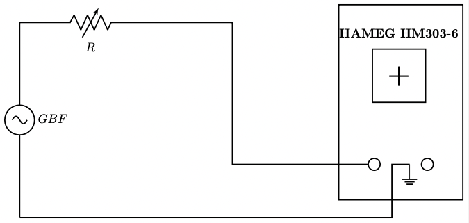


Here are circuitikz diagrams illustrating typical uses of a cathode-ray oscilloscope (HAMEG HM303-6).
Frequency measurement circuit:
\documentclass[border=5pt]{standalone}
\usepackage{circuitikz}
\begin{document}
\begin{circuitikz}
	\draw [line width=1] (1,1.5) to[sinusoidal voltage source, l_=$GBF$, line width = 0.5]
		(1,7) -- (3,7)
	to [capacitor, l_=$C$,line width = 0.5](3,4)
	to[resistor, l_=$R$,line width = 0.5] (3,1.5)
	-- (1,1.5);

	\draw [line width=1] (3,7)
	--(5,7)
	--(5,3)
	--(10,3);
	\draw (10,3) node[ocirc, scale=3, line width = 1] {};

	\draw[line width=1] (3,4)
	--(11.5,4)
	--(11.5,3);
	\draw (11.5,3) node[ocirc, scale=3,line width = 1] {};

	\draw[line width=1] (3,1.5)
	--(10.5,1.5)
	--(10.5,3)
	--(11,3);
	\draw (11,3) node[ground,line width = 0.5] {};

	\draw[line width=1] (9,7.5) rectangle (12.5, 2);
	\draw[line width=1] (10.7,5.5) node[draw, rectangle, minimum size=2cm] {};
	% Horizontal line passing through the center
	\draw (9.7,5.5) -- (11.7,5.5);
	% Vertical line passing through the center
	\draw (10.7,4.5) -- (10.7,6.5);
	% Sinusoidal curve: amplitude 6 V, centered at 5.5
	\draw[domain=9.7:11.7, smooth, variable=\x, samples=100]
	plot ({\x},{5.5 + 1.0*sin(180*(\x-9.7))});
	% Origin marked
	\node at (10.7,5.5) [below left] {$0$};
\end{circuitikz}
\end{document}
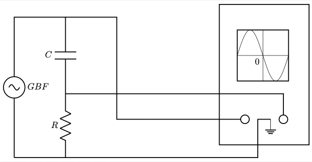
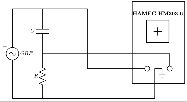
Phase-shift measurement circuit:
\documentclass[border=5pt]{standalone}
\usepackage{circuitikz}
\begin{document}
\begin{circuitikz}
	\draw [line width=1] (1,1) to[sinusoidal voltage source, l_=$GBF$, line width = 0.5]
		(1,7) -- (3,7)
	to [capacitor, l_=$C$,line width = 0.5](3,4)
	to[resistor, l_=$R$,line width = 0.5] (3,1)
	-- (1,1);

	\draw [line width=1] (3,7)
	--(6,7)
	--(6,3)
	--(10,3);
	\draw (10,3) node[ocirc, scale=3, line width = 1] {};

	\draw[line width=1] (3,4)
	--(11.5,4)
	--(11.5,3);
	\draw (11.5,3) node[ocirc, scale=3,line width = 1] {};

	\draw[line width=1] (3,1)
	--(10.5,1)
	--(10.5,3)
	--(11,3);
	\draw (11,3) node[ground,line width = 0.5] {};

	\draw[line width=1] (9,7.5) rectangle (12.5, 2);
	\draw[line width=1] (10.7,5.5) node[draw, rectangle, minimum size=1.5cm] {\Huge +};
	\draw (10.7,6.7) node {\textbf{HAMEG HM303-6}};

	\node at (0.5,4.5) {$\boldmath{+}$};
	\node at (0.5,3.5) {$\boldmath{-}$};
\end{circuitikz}
\end{document}
Internal resistance and capacitance measurement circuit:
\documentclass[border=5pt]{standalone}
\usepackage{circuitikz}
\begin{document}
\begin{circuitikz}
	\draw [line width=1] (0,1.5) to[sinusoidal voltage source, l_=$GBF$, line width = 0.5]
		(0,7) to[variable resistor, l_=$R$,line width = 0.5] (4,7)
	--(6,7)
	--(6,3)
	--(10,3);
	\draw (10,3) node[ocirc, scale=3,line width = 1] {};

	\draw (11.5,3) node[ocirc, scale=3,line width = 1] {};

	\draw[line width=1] (0,1.5)
	--(10.5,1.5)
	--(10.5,3)
	--(11,3);
	\draw (11,3) node[ground,line width = 0.5] {};

	\draw[line width=1] (9,7.5) rectangle (12.5, 2);
	\draw[line width=1] (10.7,5.5) node[draw, rectangle, minimum size=1.5cm] {\Huge +};
	\draw (10.7,6.7) node {\textbf{HAMEG HM303-6}};
\end{circuitikz}
\end{document}