

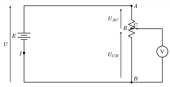
Here are circuitikz diagrams illustrating potentiometric setups.
Basic potentiometric setup (battery E, current I, potentiometer R, voltmeter, points A/B/C with U_AC, U_CB, U):
\documentclass[border=5pt]{standalone}
\usepackage{circuitikz}
\newcommand{\voltmeter}{node[circle,draw]{{\color{black!70}\textbf{V}}}}
\newcommand{\amperemeter}{node[circle,draw]{{\color{black!70}\textbf{A}}}}
\begin{document}
		\begin{circuitikz}
		\draw [line width=1] (-1,0) --(-1,1) to[battery, l=$E$, i=$I$, invert, line width=0.5]
			(-1,5) --(6,5)
		to[potentiometer, l_=$R$] (6,2)
		--(6,0)
		--(-1,0);
		\draw [line width=1] (6,3.5) -- (8,3.5);
		\draw[line width = 1] (6,0) --(8,0) --(8,1.63);
		\draw [line width=1](8,2) \voltmeter (8,3.5);
		\draw [line width=1](8,3.5) --(8,2.37);

		% Points
		\draw (6,5) node[ right] {$A$};
		\draw (6,0) node[above right] {$B$};
		\draw (6,3.5) node[above right] {$C$};
		\draw (6,5) node {$\bullet$};
		\draw (6,0) node {$\bullet$};
		\draw (6,3.5) node {$\bullet$};

		% Flèches de tension
		\draw[>=stealth,->, thick] (5.3,3.5) -- (5.3,4.8) node[midway,left] {$U_{AC}$};
		\draw[>=stealth,->, thick] (5.3,0.3) -- (5.3,3.3) node[midway,left] {$U_{CB}$};
		\draw[>=stealth,->, thick] (-1.9,0)  -- (-1.9,5)  node[midway,left] {$U$};
	\end{circuitikz}
\end{document}
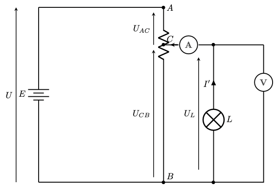
Potentiometric setup with a lamp (ammeter, voltmeter, lamp L):
\documentclass[border=5pt]{standalone}
\usepackage{circuitikz}
\newcommand{\voltmeter}{node[circle,draw]{{\color{black!70}\textbf{V}}}}
\newcommand{\amperemeter}{node[circle,draw]{{\color{black!70}\textbf{A}}}}
\tikzset{
	pics/interruptor/.style={
		code = {
			\draw (0,0) -- (1,0);
			\draw (2,0) -- (3,0);
			\draw (1,0) -- (1.8,0.5);
			\fill (1,0) circle (2pt);
			\fill (2,0) circle (2pt);}}}
\begin{document}
	\begin{circuitikz}
		\draw [line width=1] (-1,-2) to[battery, l=$E$,  invert, line width=0.5] (-1,5);
		\draw [line width=1] (-1,5)
		--(4,5)
		to[potentiometer,line width=0.7] (4,2)
		--(4,-2)
		--(-1,-2);
		\draw [line width=1] (4,3.5)
		--(4.6,3.5);
		\draw [line width=1] (5,3.5)
		\amperemeter (5.5,3.5);
		\draw [line width=1]  (5.4,3.5)
		-- (8,3.5);
		\draw[line width = 1] (4,-2)
		--(8,-2)
		--(8,1.63);
		\draw [line width=1](8,2)
		\voltmeter (8,3.5);
		\draw [line width=1](8,3.5)
		--(8,2.37);
		\draw [line width=1] (6,-2)
		to [lamp, l_=$L$,i=$I'$, line width=0.7] (6,3)
		--(6,3.5);

		\draw (4,5) node[ right] {$A$};
		\draw (4,-2) node[above right] {$B$};
		\draw (4,3.5) node[above right] {$C$};
		\draw (4,5) node {$\bullet$};
		\draw (4,-2) node {$\bullet$};
		\draw (4,3.5) node {$\bullet$};
		\draw (6,-2) node {$\bullet$};
		\draw (6,3.5) node {$\bullet$};

		\draw[>=stealth,->, thick] (3.6,3.5)  -- (3.6,4.8) node[midway,left] {$U_{AC}$};
		\draw[>=stealth,->, thick] (5.4,-1.5) -- (5.4,3)   node[midway,left] {$U_{L}$};
		\draw[>=stealth,->, thick] (-1.9,-2)  -- (-1.9,5)  node[midway,left] {$U$};
		\draw[>=stealth,->, thick] (3.6,-1.8) -- (3.6,3.3) node[midway,left] {$U_{CB}$};
		\end{circuitikz}
\end{document}
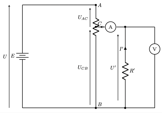
Potentiometric setup with an added resistor R’:
\documentclass[border=5pt]{standalone}
\usepackage{circuitikz}
\newcommand{\voltmeter}{node[circle,draw]{{\color{black!70}\textbf{V}}}}
\newcommand{\amperemeter}{node[circle,draw]{{\color{black!70}\textbf{A}}}}
\tikzset{
	pics/interruptor/.style={
		code={
			\draw (0,0) -- (1,0);
			\draw (2,0) -- (3,0);
			\draw (1,0) -- (1.8,0.5);
			\fill (1,0) circle (2pt);
			\fill (2,0) circle (2pt);}}}
\begin{document}
	\begin{circuitikz}
		\draw [line width=1] (-1,-2) to[battery, l=$E$,  invert, line width=0.5] (-1,5);
		\draw [line width=1] (-1,5)
		--(4,5)
		to[potentiometer,line width=0.7] (4,2)
		--(4,-2)
		--(-1,-2);
		\draw [line width=1] (4,3.5)
		--(4.6,3.5);
		\draw [line width=1] (5,3.5)
		\amperemeter (5.5,3.5);
		\draw [line width=1]  (5.4,3.5)
		-- (8,3.5);
		\draw[line width = 1] (4,-2)
		--(8,-2)
		--(8,1.63);
		\draw [line width=1](8,2)
		\voltmeter (8,3.5);
		\draw [line width=1](8,3.5)
		--(8,2.37);
		\draw [line width=1] (6,-2)
		to [resistor, l_=$R'$,i=$I'$, line width=0.7] (6,3)
		--(6,3.5);

		\draw (4,5) node[ right] {$A$};
		\draw (4,-2) node[above right] {$B$};
		\draw (4,3.5) node[above right] {$C$};
		\draw (4,5) node {$\bullet$};
		\draw (4,-2) node {$\bullet$};
		\draw (4,3.5) node {$\bullet$};
		\draw (6,-2) node {$\bullet$};
		\draw (6,3.5) node {$\bullet$};

		\draw[>=stealth,->, thick] (3.6,3.5) -- (3.6,4.8) node[midway,left] {$U_{AC}$};
		\draw[>=stealth,->, thick] (5.5,-1.5) -- (5.5,3) node[midway,left] {$U'$};
		\draw[>=stealth,->, thick] (-1.9,-2) -- (-1.9,5) node[midway,left] {$U$};
		\draw[>=stealth,->, thick] (3.6,-1.8) -- (3.6,3.3) node[midway,left] {$U_{CB}$};
	\end{circuitikz}
\end{document}
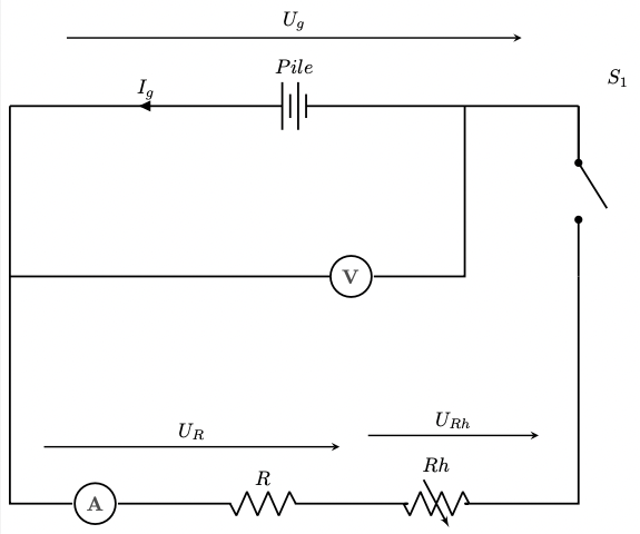
Potentiometric setup with a cell, galvanometer, switch, and rheostat (Pile, Ig, S1, Rh, R, U_g, U_R, U_Rh):
\documentclass[border=5pt]{standalone}
\usepackage{circuitikz}
\newcommand{\voltmeter}{node[circle,draw]{{\color{black!70}\textbf{V}}}}
\newcommand{\amperemeter}{node[circle,draw]{{\color{black!70}\textbf{A}}}}
\tikzset{
	pics/interruptor/.style={
		code={
			\draw (0,0) -- (1,0);
			\draw (2,0) -- (3,0);
			\draw (1,0) -- (1.8,0.5);
			\fill (1,0) circle (2pt);
			\fill (2,0) circle (2pt);}}}
\begin{document}
		\begin{circuitikz}
		% Pile et interrupteur
		\draw [line width=1] (-3,0) to[battery, l=$Pile$, i=$I_g$, line width=0.5] (7,0);
		\pic[rotate=270, line width=1] at (7,0) {interruptor};
		\node at (7.7,0.5) {$S_1$};

		% Branche du bas avec Rh, R et ampèremètre
		\draw [line width=1] (7,0) --(7,-1);%-- (7,-4)
		\draw [line width=1] (7,-3)--(7,-7)--(5,-7)
		to[variable resistor ,l_=$Rh$, line width = 0.5, invert] (4,-7)
		to[ resistor, l_=$R$, line width = 0.5, invert] (-1.1,-7);
		\draw[line width=1] (-1.5,-7) \amperemeter (-1,-7);
		\draw[line width = 1] (-1.9,-7)--(-3,-7)--(-3,0);

		% Voltmètre en parallèle sur R
		\draw [line width=1] (5,0) -- (5,-3) -- (3.4,-3);
		\draw [line width=1] (3,-3) \voltmeter (2.63,-3) -- (-3,-3);

		% Flèches de tension
		\draw[>=stealth,->, thick] (-2,1.2) -- (6,1.2) node[midway,above] {$U_{g}$};
		\draw[>=stealth,->, thick] (-2.4,-6) -- (2.8,-6) node[midway,above] {$U_{R}$};
		\draw[>=stealth,->, thick] (3.3,-5.8) -- (6.3,-5.8) node[midway,above] {$U_{Rh}$};
	\end{circuitikz}
\end{document}