")


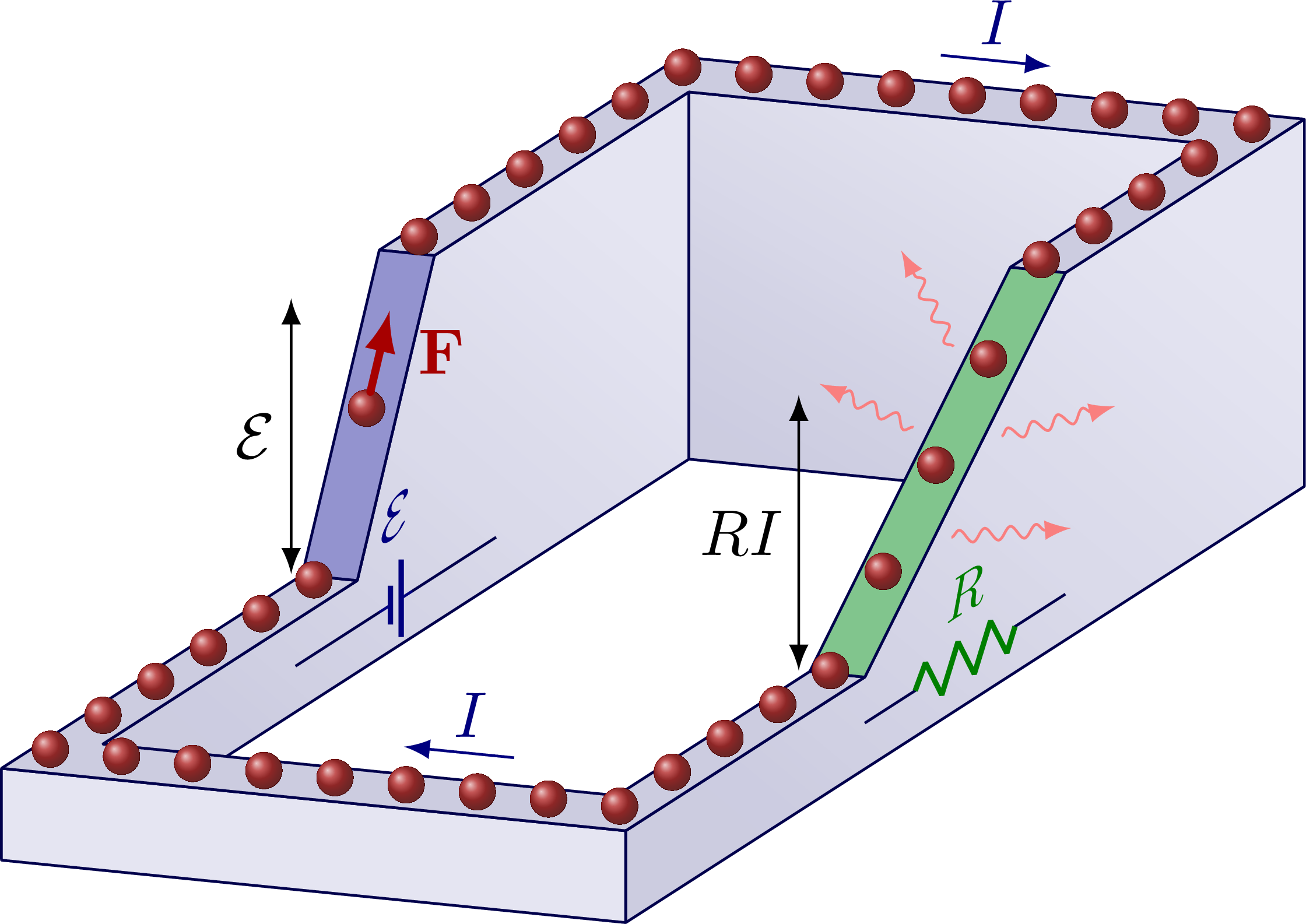
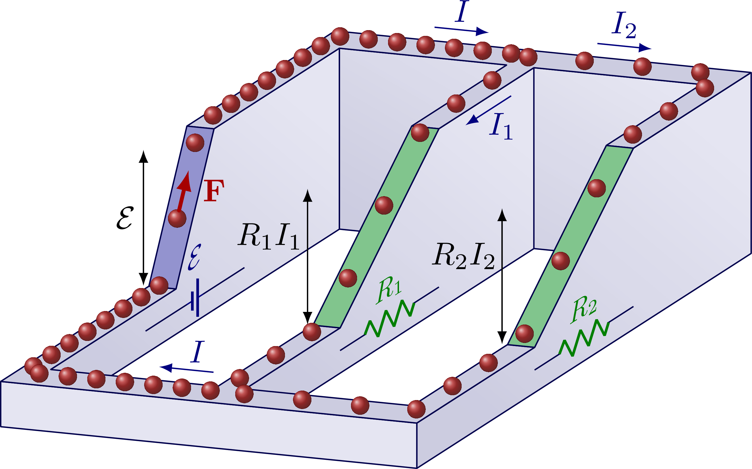
The gravitational potential energy analogy for voltage in an electric circuit. Inspired by Eugene Khutoryansky’s YouTube videos. For more related figures, please see these figures on Kirchhof’s laws, or the Electric Engineering category.
Single battery/EMF and single resistor:
Two resistors in series:

Two resistors in parallel:
Edit and compile if you like:
% Author: Izaak Neutelings (December 2021)
% Inspired by Eugene Khutoryansky
% https://www.youtube.com/watch?v=m4jzgqZu-4s
\documentclass[border=3pt,tikz]{standalone}
\usetikzlibrary{3d} % for canvas is
\usepackage{physics}
\usepackage[siunitx]{circuitikz}
\usepackage[outline]{contour} % glow around text
\usetikzlibrary{arrows}
%\usetikzlibrary{angles,quotes} % for pic (angle labels)
\usetikzlibrary{decorations.pathmorphing,decorations.markings} % for random steps & snake
\tikzset{>=latex} % for LaTeX arrow head
\usepackage{xcolor}
\contourlength{1.5pt}

\colorlet{myred}{red!65!black}
\colorlet{myblue}{blue!70!black}
\colorlet{mydarkblue}{blue!30!black}
\colorlet{Icol}{blue!50!black}
\colorlet{Ccol}{orange!90!black}
\colorlet{Rcol}{green!50!black}
\colorlet{sidecol}{blue!50!black!10}
\colorlet{darksidecol}{blue!40!black!20}
\colorlet{topcol}{blue!40!black!20}

\newcommand\EMF{\mathcal{E}}
\tikzstyle{EMF}=[battery1,color=Icol,Icol,l_=\small$\EMF$,thin,/tikz/circuitikz/bipoles/length=20pt]
\tikzstyle{thick R}=[R,color=Rcol,Rcol,l=\small$R$,/tikz/circuitikz/bipoles/length=22pt]
\tikzstyle{force}=[->,myred,very thick,line cap=round]
\tikzstyle{radiation}=[-{Latex[length=4,width=3]},red!95!black!50,thin,decorate,
                       decoration={snake,amplitude=1,segment length=4,post length=3}]
\tikzstyle{side face}=[mydarkblue,fill=sidecol,rounded corners=0.1]
\tikzstyle{top face}=[side face,fill=topcol]
\tikzset{
  shadow face/.style={side face,top color=sidecol,bottom color=darksidecol,shading angle=#1},
  EFieldLine/.default=30
}


\begin{document}


% SIMPLE CIRCUIT
\def\w{0.3}  % wire width
\def\h{0.5}  % lowest height
\def\W{2.8}  % total circuit width
\def\H{2.0}  % total circuit height
\def\L{3.8}  % total circuit length
\def\LB{0.5} % battery length
\def\LR{1.3} % resistor length
\def\N{40}   % number of balls
\pgfmathsetmacro\yBa{\L/2-\LB/2} % ya position battery
\pgfmathsetmacro\yBb{\L/2+\LB/2} % yb position battery
\pgfmathsetmacro\yRa{\L/2+\LR/2} % ya position resistor
\pgfmathsetmacro\yRb{\L/2-\LR/2} % yb position resistor
\begin{tikzpicture}[x={(1cm,-0.1cm)},y={(0.84cm,0.54cm)},z={(0,1cm)}]
  \message{Simple circuit^^J}
  \def\rad#1#2{
    \draw[radiation,canvas is xz plane at y=\yRb+\LR*#1]
      ({\W+\w/2+0.8*\w*sign(cos(#2))},{\h+(\H-\h)*#1}) --++ (#2:{2*\w+0.2*cos(#2)*\w});
  }

  % SIDE FACES
  %\draw[blue,canvas is yx plane at z=0] % help lines
  %  (0,0) rectangle (\L,\W);
  %\draw[red,canvas is yx plane at z=0] % help lines
  %  (-\w,-\w) rectangle (\L+\w,\W+\w);
  \draw[shadow face=-40,canvas is yz plane at x=0] % inner side
    (0,0) |- (\yBa,\h) --++ (\LB,\H-\h) -| (\L,0) -- cycle;
  \draw[shadow face=-30,canvas is xz plane at y=\L] % inner back
    (0,0) rectangle (\W,\H);
  \draw[shadow face=-40,canvas is yz plane at x=\W+\w] % outer side
    (-\w,0) |-++ (\w+\yRb,\h) --++ (\LR,\H-\h) -| (\L+\w,0) -- cycle;
  \draw[side face,canvas is xz plane at y=-\w] % outer low front
    (-\w,0) rectangle (\W+\w,\h);

  % TOP FACES
  \draw[top face,canvas is xy plane at z=\h] % lowest face
    (-\w,-\w) |- (0,\yBa) -- (0,0)
    -|++ (\W,\yRb) -|++ (\w,-\yRb-\w) -- cycle;
  \draw[top face,canvas is xy plane at z=\H] % highest face
    (0,\yBb) |- (\W,\L) |- (\W+\w,\yRa)
    |- (-\w,\L+\w) |- cycle;
  \draw[top face,fill=topcol!80!blue!90!black] % slope battery
    (0,\yBa,\h) --++ (0,\LB,\H-\h) --++ (-\w,0,0) --++ (0,-\LB,\h-\H) -- cycle;
  \draw[top face,fill=topcol!70!green!90!black] % slope resistor
    (\W+\w,\yRb,\h) --++ (0,\LR,\H-\h) --++ (-\w,0,0) --++ (0,-\LR,\h-\H) -- cycle;

  % CIRCUIT SYMBOLS
  \draw[mydarkblue,canvas is yz plane at x=0,transform shape] % resistor symbol
     (\yRa,\h/2) to[EMF]++ (-\LR,0);
  \draw[mydarkblue,canvas is yz plane at x=\W+\w,transform shape] % resistor symbol
     (\yRb,\h/2) to[thick R]++ (\LR,0);

  % ELECTRONS
  %\draw[green,canvas is yx plane at z=\h] % help lines
  %  (-\w/2,-\w/2) rectangle (\yBa+\w/2,\W+\w/2);
  %\draw[green,canvas is yx plane at z=\H] % help lines
  %  (\yBb,-\w/2) rectangle (\L+\w/2,\W+\w/2);
  \pgfmathsetmacro\tBa{0.3*(\w/2+\yBa)/(\L+\w)} % ta position battery
  \pgfmathsetmacro\tBb{0.3*(\w/2+\yBb)/(\L+\w)} % tb position battery
  \pgfmathsetmacro\tRa{0.5+0.3*(\w/2+\L-\yRa)/(\L+\w)} % ta position resistor
  \pgfmathsetmacro\tRb{0.5+0.3*(\w/2+\L-\yRb)/(\L+\w)} % tb position resistor
  \foreach \i [evaluate={\t=\i/\N;
                         \x=-\w/2+(\t-0.3)*(\W+\w)/0.2*(0.3<\t && \t<=0.5)
                                 +(\W+\w)*(0.5<\t)
                                 -(\t-0.8)*(\W+\w)/0.2*(0.8<\t);
                         \y=-\w/2+\t*(\L+\w)/0.3*(\t<=0.3)
                                 +(\L+\w)*(0.3<\t && \t<=0.8)
                                 -(\t-0.5)*(\L+\w)/0.3*(0.5<\t && \t<=0.8);
                         \z=\h+(\H-\h)/(\tBb-\tBa)*(\t-\tBa)*(\tBa<\t && \t<=\tBb)
                              +(\H-\h)*(\tBb<\t && \t<=\tRa)
                              +(\H-\h)/(\tRa-\tRb)*(\t-\tRb)*(\tRa<\t && \t<=\tRb);
               }] in {1,...,\N}{
    \coordinate (E\i) at (\x-0.2*\w,\y+0.2*\w,\z); % extra shift for 3D ball perspective
    \fill[ball color=myred,x={(1cm,0)},y={(0,1cm)}]
      (E\i) circle (0.1); %node[below,scale=0.2] {\i};
    \fill[myred!40,x={(1cm,0)},y={(0,1cm)},opacity=0.25]
      (E\i) circle (0.098);
  }

  % RADIATION
  \rad{0.35}{10}
  \rad{0.60}{160}
  \rad{0.60}{20}
  \rad{0.80}{120}

  % LABELS
  \draw[force] (E6)++(0,\LB*0.05,{(\H-\h)*0.05}) --++ (0,\LB*0.25,{(\H-\h)*0.25})
    node[pos=0.5,right=2] {$\vb{F}$};
  \draw[<->] % EMF arrow
    (-1.2*\w,\yBa,\h) --++ (0,0,\H-\h) node[pos=0.5,left=-1] {$\EMF$};
  \draw[<->] % resistor arrow
    (\W-0.2*\w,\yRb,\h) --++ (0,0,\H-\h) node[pos=0.5,left=-1] {$RI$};
  \draw[->,Icol] % current arrow
    (0.4*\W,\L+\w,\H+0.5*\w) --++ (2*\w,0,0) node[midway,above=-1] {$I$};
  \draw[->,Icol] % current arrow
    (0.8*\W,0,\h+0.5*\w) --++ (-2*\w,0,0) node[pos=0.4,above=-1] {$I$};

\end{tikzpicture}


% CIRCUIT - RESISTOR IN SERIES
\begin{tikzpicture}[x={(1cm,-0.1cm)},y={(0.84cm,0.54cm)},z={(0,1cm)}]
  \message{Resistor in series^^J}
  \def\LR{0.7} % resistor length
  \pgfmathsetmacro\yRAa{2*\L/3+\LR/2} % ya position resistor 1
  \pgfmathsetmacro\yRAb{2*\L/3-\LR/2} % yb position resistor 1
  \pgfmathsetmacro\yRBa{\L/3+\LR/2}   % yc position resistor 2
  \pgfmathsetmacro\yRBb{\L/3-\LR/2}   % yd position resistor 2
  \pgfmathsetmacro\hm{\h/2+\H/2}      % height between resistor 1 and 2

  % SIDE FACES
  \draw[shadow face=-40,canvas is yz plane at x=0] % inner side
    (0,0) |- (\yBa,\h) --++ (\LB,\H-\h) -| (\L,0) -- cycle;
  \draw[shadow face=-30,canvas is xz plane at y=\L] % inner back
    (0,0) rectangle (\W,\H);
  \draw[shadow face=-40,canvas is yz plane at x=\W+\w] % outer side
    (-\w,0) |-++ (\yRBb,\h) -- (\yRBa,\hm) -- (\yRAb,\hm) -- (\yRAa,\H) -| (\L+\w,0) -- cycle;
  \draw[side face,canvas is xz plane at y=-\w] % outer low front
    (-\w,0) rectangle (\W+\w,\h);

  % TOP FACES
  \draw[top face,canvas is xy plane at z=\h] % lowest face
    (-\w,-\w) |- (0,\yBa) -- (0,0)
    -|++ (\W,\yRBb) -|++ (\w,-\yRBb-\w) -- cycle;
  \draw[top face,canvas is xy plane at z=\H] % highest face
    (0,\yBb) |- (\W,\L) |- (\W+\w,\yRAa)
    |- (-\w,\L+\w) |- cycle;
  \draw[top face,canvas is xy plane at z=\hm] % middle between resistor 1 & 2
    (\W,\yRBa) rectangle (\W+\w,\yRAb);
  \draw[top face,fill=topcol!80!blue!90!black] % slope battery
    (0,\yBa,\h) --++ (0,\LB,\H-\h) --++ (-\w,0,0) --++ (0,-\LB,\h-\H) -- cycle;
  \draw[top face,fill=topcol!70!green!90!black] % slope resistor 1
    (\W+\w,\yRAb,\hm) --++ (0,\LR,\H-\hm) --++ (-\w,0,0) --++ (0,-\LR,\hm-\H) -- cycle;
  \draw[top face,fill=topcol!70!green!90!black] % slope resistor 2
    (\W+\w,\yRBb,\h) --++ (0,\LR,\hm-\h) --++ (-\w,0,0) --++ (0,-\LR,\h-\hm) -- cycle;

  % CIRCUIT SYMBOLS
  \draw[mydarkblue,canvas is yz plane at x=0,transform shape] % resistor symbol
     (\yRa,\h/2) to[EMF]++ (-0.3*\L,0);
  \draw[mydarkblue,canvas is yz plane at x=\W+\w,transform shape] % resistor 1 symbol
     (\L/3-0.2*\L/2,\h/2) to[thick R,l=\small$R_2$]++ (0.3*\L,0)
     -- (\L/2,\h/2) -- (2*\L/3-0.2*\L/2,\h/2) to[thick R,l=\small$R_1$]++ (0.3*\L,0);

  % ELECTRONS
  \pgfmathsetmacro\tBa{0.3*(\w/2+\yBa)/(\L+\w)} % ta position battery
  \pgfmathsetmacro\tBb{0.3*(\w/2+\yBb)/(\L+\w)} % tb position battery
  \pgfmathsetmacro\tRAa{0.5+0.3*(\w/2+\L-\yRAa)/(\L+\w)} % ta position resistor
  \pgfmathsetmacro\tRAb{0.5+0.3*(\w/2+\L-\yRAb)/(\L+\w)} % tb position resistor
  \pgfmathsetmacro\tRBa{0.5+0.3*(\w/2+\L-\yRBa)/(\L+\w)} % ta position resistor
  \pgfmathsetmacro\tRBb{0.5+0.3*(\w/2+\L-\yRBb)/(\L+\w)} % tb position resistor
  \foreach \i [evaluate={\t=\i/\N;
                         \x=-\w/2+(\t-0.3)*(\W+\w)/0.2*(0.3<\t && \t<=0.5)
                                 +(\W+\w)*(0.5<\t)
                                 -(\t-0.8)*(\W+\w)/0.2*(0.8<\t);
                         \y=-\w/2+\t*(\L+\w)/0.3*(\t<=0.3)
                                 +(\L+\w)*(0.3<\t && \t<=0.8)
                                 -(\t-0.5)*(\L+\w)/0.3*(0.5<\t && \t<=0.8);
                         \z=\h+(\H-\h)/(\tBb-\tBa)*(\t-\tBa)*(\tBa<\t && \t<=\tBb)
                              +(\H-\h)*(\tBb<\t && \t<=\tRAa)
                              +(\H-\hm)/(\tRAa-\tRAb)*(\t-\tRAb)*(\tRAa<\t && \t<=\tRAb)
                              +(\hm-\h)*(\tRAa<\t && \t<=\tRBa)
                              +(\hm-\h)/(\tRBa-\tRBb)*(\t-\tRBb)*(\tRBa<\t && \t<=\tRBb);
               }] in {1,...,\N}{
    \coordinate (E\i) at (\x-0.2*\w,\y+0.2*\w,\z); % extra shift for 3D ball perspective
    \fill[ball color=myred,x={(1cm,0)},y={(0,1cm)}]
      (E\i) circle (0.1); %node[below,scale=0.2] {\i};
    \fill[myred!40,x={(1cm,0)},y={(0,1cm)},opacity=0.25]
      (E\i) circle (0.098);
  }

  % LABELS
  \draw[force] (E6)++(0,\LB*0.05,{(\H-\h)*0.05}) --++ (0,\LB*0.25,{(\H-\h)*0.25})
    node[pos=0.5,right=2] {$\vb{F}$};
  \draw[<->] % EMF arrow
    (-1.2*\w,\yBa,\h) --++ (0,0,\H-\h) node[pos=0.5,left=-1] {$\EMF$};
  \draw[<->] % resistor 1 arrow
    (\W-0.2*\w,\yRAb,\hm) --++ (0,0,\H-\hm) node[pos=0.5,left=-1] {$R_1I$};
  \draw[<->] % resistor 2 arrow
    (\W-0.2*\w,\yRBb,\h) --++ (0,0,\hm-\h) node[pos=0.5,left=-1] {$R_2I$};
  \draw[->,Icol] % current arrow
    (0.4*\W,\L+\w,\H+0.5*\w) --++ (2*\w,0,0) node[midway,above=-1] {$I$};
  \draw[->,Icol] % current arrow
    (0.8*\W,0,\h+0.5*\w) --++ (-2*\w,0,0) node[pos=0.4,above=-1] {$I$};

\end{tikzpicture}


% CIRCUIT - RESISTOR IN PARALLEL
\begin{tikzpicture}[x={(1cm,-0.1cm)},y={(0.84cm,0.54cm)},z={(0,1cm)}]
  \message{Resistor in parallel^^J}
  \def\W{4.0} % total circuit width
  \def\N{55}  % number of balls
  \pgfmathsetmacro\xMa{\W/2-\w/2} % xa position middle wire
  \pgfmathsetmacro\xMb{\W/2+\w/2} % xb position middle wire

  % SIDE FACES
  \draw[shadow face=-40,canvas is yz plane at x=0] % inner side
    (0,0) |- (\yBa,\h) --++ (\LB,\H-\h) -| (\L,0) -- cycle;
  \draw[shadow face=-30,canvas is xz plane at y=\L] % inner back
    (0,0) rectangle (\W,\H);
  \draw[shadow face=-40,canvas is yz plane at x=\xMb] % middle inner side
    (0,0) |- (\yRb,\h) --++ (\LR,\H-\h) -| (\L,0) -- cycle;
  \draw[shadow face=-40,canvas is yz plane at x=\W+\w] % outer side
    (-\w,0) |-++ (\w+\yRb,\h) --++ (\LR,\H-\h) -| (\L+\w,0) -- cycle;
  \draw[side face,canvas is xz plane at y=-\w] % outer low front
    (-\w,0) rectangle (\W+\w,\h);

  % TOP FACES
  \draw[top face,canvas is xy plane at z=\h] % lowest face
    (-\w,-\w) |- (0,\yBa) |- (\xMa,0) |-++ (\w,\yRb) |- (\W,0)
    |-++ (\w,\yRb) |- cycle;
  \draw[top face,canvas is xy plane at z=\H] % highest face
    (0,\yBb) |- (\xMa,\L) |- (\xMa+\w,\yRa)
    |- (\W,\L) |- (\W+\w,\yRa) |- (-\w,\L+\w) |- cycle;
  \draw[top face,fill=topcol!80!blue!90!black] % slope battery
    (0,\yBa,\h) --++ (0,\LB,\H-\h) --++ (-\w,0,0) --++ (0,-\LB,\h-\H) -- cycle;
  \draw[top face,fill=topcol!70!green!90!black] % slope resistor
    (\xMb,\yRb,\h) --++ (0,\LR,\H-\h) --++ (-\w,0,0) --++ (0,-\LR,\h-\H) -- cycle;
  \draw[top face,fill=topcol!70!green!90!black] % slope resistor
    (\W+\w,\yRb,\h) --++ (0,\LR,\H-\h) --++ (-\w,0,0) --++ (0,-\LR,\h-\H) -- cycle;

  % CIRCUIT SYMBOLS
  \draw[mydarkblue,canvas is yz plane at x=0,transform shape] % resistor symbol
     (\yRa,\h/2) to[EMF]++ (-\LR,0);
  \draw[mydarkblue,canvas is yz plane at x=\xMb,transform shape] % resistor symbol
     (\yRb,\h/2) to[thick R,l=\small$R_1$]++ (\LR,0);
  \draw[mydarkblue,canvas is yz plane at x=\W+\w,transform shape] % resistor symbol
     (\yRb,\h/2) to[thick R,l=\small$R_2$]++ (\LR,0);

  % ELECTRONS LEFT
  \pgfmathsetmacro\NL{int(\N*2*(\L+\W+2*\w)/(4*\L+3*\W+7*\w))} % number of electrons left
  \pgfmathsetmacro\NR{int(\N-\NL)} % number of electrons right
  \pgfmathsetmacro\tBa{0.22+0.56*(\w/2+\yBa)/(\L+\w)} % ta position battery
  \pgfmathsetmacro\tBb{0.22+0.56*(\w/2+\yBb)/(\L+\w)} % tb position battery
  \foreach \i [evaluate={\t=\i/\NL-0.01;
                         \x=(\W/2-\t*(\W/2+\w/2)/0.22)*(\t<=0.22)
                              -\w/2*(0.22<\t)
                              +(\t-0.78)*(\W/2+\w/2)/0.22*(0.78<\t);
                         \y=\L+\w/2
                              -(\t-0.22)*(\L+\w)/0.56*(0.22<\t && \t<=0.78)
                              -(\L+\w)*(0.78<\t);
                         \z=\H-(\H-\h)/(\tBb-\tBa)*(min(\t,\tBb)-\tBa)*(\tBa<\t);
               }] in {1,...,\NL}{
    \coordinate (E\i) at (\x-0.2*\w,\y+0.2*\w,\z); % extra shift for 3D ball perspective
    \fill[ball color=myred,x={(1cm,0)},y={(0,1cm)}]
      (E\i) circle (0.1);
    \fill[myred!40,x={(1cm,0)},y={(0,1cm)},opacity=0.25]
      (E\i) circle (0.098);
  }

  % ELECTRONS RIGHT (half density)
  \pgfmathsetmacro\tRa{0.36*(\w/2+\yRb)/(\L+\w)} % ta position resistor 1
  \pgfmathsetmacro\tRb{0.36*(\w/2+\yRa)/(\L+\w)} % tb position resistor 1
  \pgfmathsetmacro\tZa{0.5+0.36*(\w/2+\yRb)/(\L+\w)} % ta position resistor 2
  \pgfmathsetmacro\tZb{0.5+0.36*(\w/2+\yRa)/(\L+\w)} % tb position resistor 2
  \foreach \i [evaluate={\t=\i/\NR-0.018;
                         \x=\W/2+(\t-0.36)*(\W/2+\w/2)/0.14*(0.36<\t && \t<=0.5)
                                 +(\W/2+\w/2)*(0.5<\t)
                                 -(\t-0.86)*(\W/2+\w/2)/0.14*(0.86<\t);
                         \y=-\w/2+\t*(\L+\w)/0.36*(\t<=0.36)
                                 +(\L+\w)*(0.36<\t && \t<=0.86)
                                 -(\t-0.5)*(\L+\w)/0.36*(0.5<\t && \t<=0.86);
                         \z=\h+(\H-\h)/(\tRb-\tRa)*(\t-\tRa)*(\tRa<\t && \t<=\tRb)
                              +(\H-\h)*(\tRb<\t && \t<=\tZb)
                              -(\H-\h)/(\tZb-\tZa)*(\t-\tZa)*(\tZa<\t && \t<=\tZb);
               }] in {1,...,\NR}{
    \coordinate (F\i) at (\x-0.2*\w,\y+0.2*\w,\z); % extra shift for 3D ball perspective
    \fill[ball color=myred,x={(1cm,0)},y={(0,1cm)}]
      (F\i) circle (0.1); %node[below,scale=0.2] {\i};
    \fill[myred!40,x={(1cm,0)},y={(0,1cm)},opacity=0.25]
      (F\i) circle (0.098);
  }

  % LABELS
  \draw[force] (E16)++(0,\LB*0.05,{(\H-\h)*0.05}) --++ (0,\LB*0.25,{(\H-\h)*0.25})
    node[pos=0.5,right=2] {$\vb{F}$};
  \draw[<->] % EMF arrow
    (-1.2*\w,\yBa,\h) --++ (0,0,\H-\h) node[pos=0.5,left=-1] {$\EMF$};
  \draw[<->] % resistor arrow
    (\W/2-0.7*\w,\yRb,\h) --++ (0,0,\H-\h) node[pos=0.65,left=-2] {$R_1I_1$};
  \draw[<->] % resistor arrow
    (\W-0.2*\w,\yRb,\h) --++ (0,0,\H-\h) node[pos=0.65,left=-2] {$R_2I_2$};

  % LABELS CURRENTS
  \draw[->,Icol] % current arrow
    (0.2*\W,\L+\w,\H+0.5*\w) --++ (2*\w,0,0) node[midway,above=-1] {$I$};
  \draw[->,Icol] % current arrow I_1
    (\W/2+\w/2,\L-\w,\H-0.5*\w) --++ (0,-2*\w,0) node[pos=0.2,below=0] {$I_1$};
  \draw[->,Icol] % current arrow I_2
    (0.65*\W,\L+\w,\H+0.5*\w) --++ (2*\w,0,0) node[midway,above=-1] {$I_2$};
  \draw[->,Icol] % current arrow
    (0.45*\W,0,\h+0.5*\w) --++ (-2*\w,0,0) node[pos=0.3,above=-1] {$I$};

\end{tikzpicture}


\end{document}
Click to download: electric_circuit_voltage_3d.tex • electric_circuit_voltage_3d.pdf
Open in Overleaf: electric_circuit_voltage_3d.tex


