")


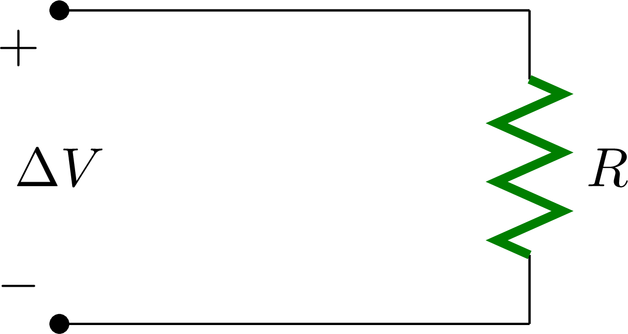
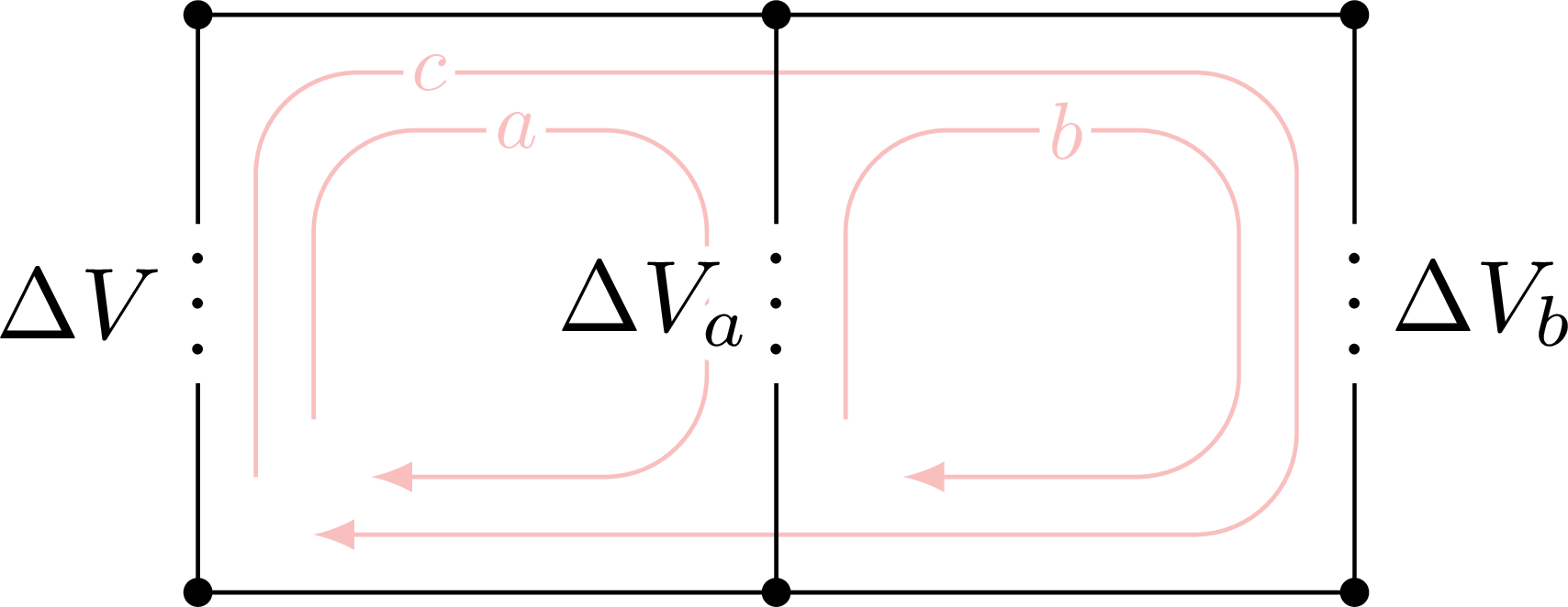
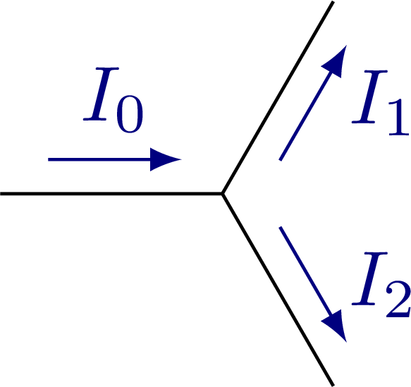
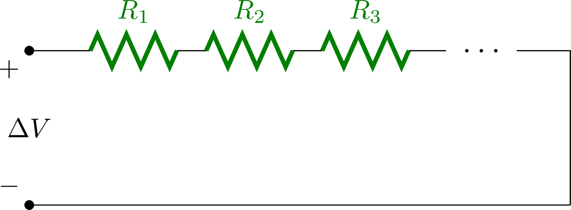
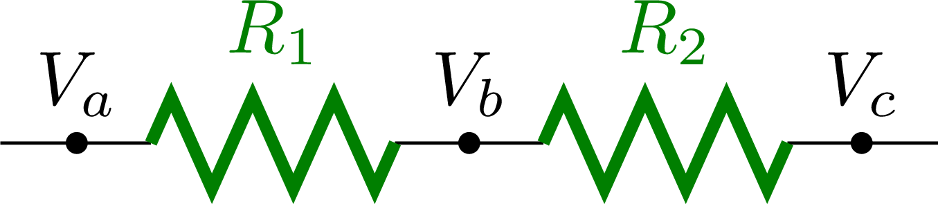
Some basic circuit diagrams with one resistor, or more in parallel or series, as well as current branches to study Kirchhoff’s circuit laws.
For more related figures, please see the “circuits” tag.


Edit and compile if you like:
% Author: Izaak Neutelings (Februari, 2020)
% http://texample.net/tikz/examples/tag/circuitikz/
% http://texample.net/tikz/examples/circuitikz/
% https://www.overleaf.com/learn/latex/CircuiTikz_package
% http://texdoc.net/texmf-dist/doc/latex/circuitikz/circuitikzmanual.pdf
% http://repositorios.cpai.unb.br/ctan/graphics/pgf/contrib/circuitikz/circuitikzmanual.pdf
\documentclass[border=3pt,tikz]{standalone}
\usepackage{amsmath} % for \dfrac
\usepackage{physics}
\usepackage{tikz,pgfplots}
\usepackage[siunitx]{circuitikz} %[symbols]
\usepackage[outline]{contour} % glow around text
\usetikzlibrary{arrows}
\usetikzlibrary{decorations.markings}
\tikzset{>=latex} % for LaTeX arrow head
\usepackage{xcolor}
\colorlet{Icol}{blue!50!black}
\colorlet{Ccol}{orange!90!black}
\colorlet{Rcol}{green!50!black}
\colorlet{loopcol}{red!90!black!25}
\colorlet{pluscol}{red!60!black}
\colorlet{minuscol}{blue!60!black}
\newcommand\EMF{\mathcal{E}} %\varepsilon}
%\tikzstyle{charged}=[top color=blue!20,bottom color=blue!40,shading angle=10]
\contourlength{1.5pt}
\tikzstyle{EMF}=[battery1,l=$\EMF$]
\tikzstyle{internal R}=[R,color=Rcol,Rcol,l=$r$,/tikz/circuitikz/bipoles/length=30pt]
\tikzstyle{loop}=[->,red!90!black!25]
\tikzstyle{loop label}=[loopcol,fill=white,scale=0.8,inner sep=1]
\tikzstyle{thick R}=[R,color=Rcol,thick,Rcol,l=$R$]
%\tikzset{
% loop/.style={thick,red!80!black!30,decoration={markings,
% mark=at position #1 with {\arrow{latex}}},
% postaction={decorate}},
% loop/.default=0.6}
\newcommand{\myvoltmeter}[2]
{ % #1 = name , #2 = rotation angle
\begin{scope}[transform shape,rotate=#2]
\draw[thick] (#1)node(){$\mathbf V$} circle (11pt);
\draw[rotate=45,-latex] (#1) +(-17pt,0) --+(17pt,0);
\end{scope}
}
\begin{document}
% RESISTOR without battery
\begin{tikzpicture}
\draw (0,2) to [short,*-] (3,2) to[R,color=Rcol,thick,l=$R$] (3,0) to [short,-*] (0,0);
\node[below left] at (0,2) {$+$};
\node[above left] at (0,0) {$-$};
\node at (0,1) {$\Delta V$};
\end{tikzpicture}
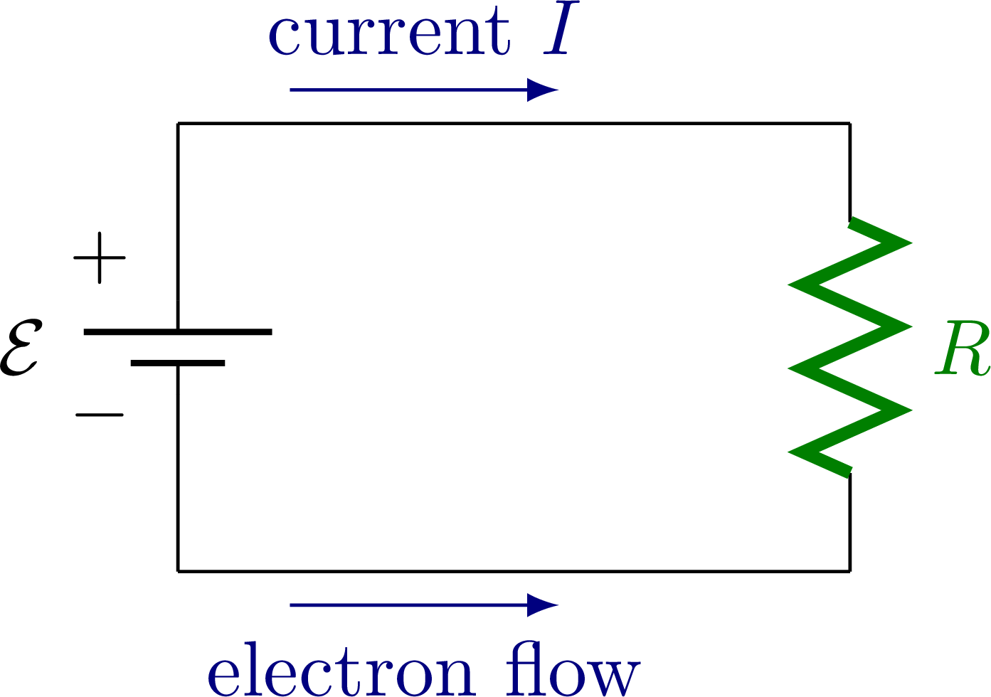
% RESISTOR with battery and arrow
\begin{tikzpicture}
\draw (0,0) to[EMF] (0,2) -- (3,2)
to[thick R] (3,0) -- (0,0);
\node at (-0.35,0.7) {$-$};
\node at (-0.35,1.4) {$+$};
\draw[->,Icol] (0.5, 2.15) --++ (1.2,0) node[midway,above=1] {current $I$};
\draw[->,Icol] (0.5,-0.15) --++ (1.2,0) node[midway,below=1] {electron flow};
\end{tikzpicture}
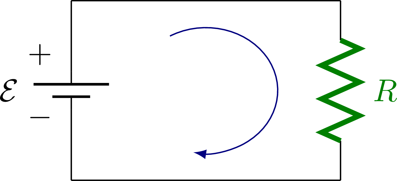
% RESISTOR with battery and arc arrow
\begin{tikzpicture}
\def\ang{120}
\def\a{0.8}
\def\b{0.7}
\draw (0,0) to[EMF] (0,2) -- (3,2)
to[thick R] (3,0) -- (0,0);
\node at (-0.35,0.7) {$-$};
\node at (-0.35,1.4) {$+$};
\draw[->,Icol] ({1.5+\a*cos(\ang)},{1+\b*sin(\ang)}) arc (120:-100:{\a} and {\b});
\end{tikzpicture}
% RESISTOR with EMF + internal resistance
\begin{tikzpicture}
\draw (0,0) to[EMF] (0,1.4)
to[internal R] (0,2.5) -- (0,3) --++ (3,0)
to[thick R] ++(0,-3) -- (0,0);
%\draw (3,2.5) --++ (0.6,0) to[voltmeter,color=white,name=M] ++(0,-2) --++ (-0.6,0);
%\myvoltmeter{M}{0} % rotate
\fill[black] (3,2.5) circle (0.05) node[right] {$V_a$};
\fill[black] (3,0.5) circle (0.05) node[right] {$V_b$};
\node at (-0.35,0.44) {$-$};
\node at (-0.35,1.05) {$+$};
\end{tikzpicture}
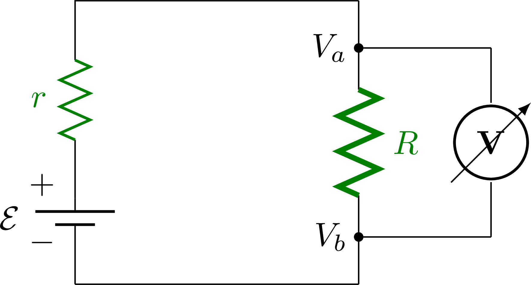
% RESISTOR with EMF + internal resistance
\begin{tikzpicture}
\draw (0,0) to[EMF] (0,1.4)
to[internal R] (0,2.5) -- (0,3) --++ (3,0)
to[thick R] ++(0,-3) -- (0,0);
\draw (3,2.5) --++ (1.4,0) to[voltmeter,color=white,name=M] ++(0,-2) --++ (-1.4,0);
\myvoltmeter{M}{0} % rotate
\fill[black] (3,2.5) circle (0.05) node[left] {$V_a$};
\fill[black] (3,0.5) circle (0.05) node[left] {$V_b$};
\node at (-0.35,0.44) {$-$};
\node at (-0.35,1.05) {$+$};
\end{tikzpicture}
%% RESISTOR with EMF + internal resistance
%\begin{tikzpicture}
% \draw (0,0) to[EMF] (0,1.4)
% to[internal R] (0,2.5) -- (0,3) --++ (3,0)
% --++ (0,-0.5) coordinate (T) --++ (-0.9,0)
% to[thick R] ++(0,-2) --++ (0.9,0) |- (0,0)
% (T) --++ (0.9,0) to[voltmeter,color=white,name=M] ++(0,-2) --++ (-0.9,0); %,l=$R$
% \myvoltmeter{M}{0} % rotate
% \node at (-0.35,0.44) {$-$};
% \node at (-0.35,1.05) {$+$};
%\end{tikzpicture}
%
%
%% RESISTOR with EMF + internal resistance + boxes
%\begin{tikzpicture}
% \draw (0,0) to[EMF] (0,1.4)
% to[internal R] (0,2.5) -- (0,3) --++ (3,0)
% --++ (0,-0.5) coordinate (T) --++ (-0.9,0)
% to[thick R] ++(0,-2) --++ (0.9,0) |- (0,0)
% (T) --++ (0.9,0) to[voltmeter,color=white,name=M] ++(0,-2) --++ (-0.9,0); %,l=$R$
% \myvoltmeter{M}{0} % rotate
% \node at (-0.35,0.44) {$-$};
% \node at (-0.35,1.05) {$+$};
% \draw[dashed,very thin] (-0.9,0.3) rectangle (0.8,2.7);
% \draw[dashed,very thin] ( 1.6,0.3) rectangle (4.5,2.7);
%\end{tikzpicture}
% RESISTOR with EMF + AMPEREMETER + VOLTMETER
\begin{tikzpicture}
\draw (0,0) to[EMF] (0,1.4)
to[internal R] (0,2.5) -- (0,3) to[ammeter] ++(3,0)
to[thick R] ++(0,-3) -- (0,0);
\draw (3,2.5) --++ (1.5,0) to[voltmeter,color=white,name=M] ++(0,-2.0) --++ (-1.5,0);
\fill[black] (3,2.5) circle (0.05);
\fill[black] (3,0.5) circle (0.05);
\myvoltmeter{M}{0} % rotate
\node at (-0.35,0.44) {$-$};
\node at (-0.35,1.05) {$+$};
\node[] at (1.5,3.65) {$R_\mathrm{A}$};
\node[] at (5.25,1.5) {$R_\mathrm{V}$};
\end{tikzpicture}
% KIRCHHOFF's RULE 1
\begin{tikzpicture}
\def\a{0.2}
\def\b{0.4}
\def\H{2}
\def\W{2}
\draw[rounded corners=10,loop] (\a,2*\a) |- (2*\W-\a,\H-\a) |- (2*\a,\a);
\draw[rounded corners=10,loop] (\b,\b+\a) |- (\W-.6*\b,\H-\b) |- (\b+\a,\b);
\draw[rounded corners=10,loop] (\W+.6*\b,\b+\a) |- (2*\W-\b,\H-\b) |- (\W+.6*\b+\a,\b);
\fill[black] (0,\H) circle (0.05); %node[above] {$V_i$};
\fill[black] (0,0) circle (0.05); %node[below] {$V_f$};
\fill[black] (\W,\H) circle (0.05); %node[above] {$V_{1a}$};
\fill[black] (\W,0) circle (0.05); %node[below] {$V_{1b}$};
\fill[black] (2*\W,\H) circle (0.05); %node[above] {$V_{2a}$};
\fill[black] (2*\W,0) circle (0.05); %node[below] {$V_{2b}$};
\draw ( 0,0) |- ++(\W,\H) |- cycle;
\draw (\W,0) -| ++(\W,\H) --++ (-2,0);
\node[fill=white,rotate=90,inner sep=2] at (0,\H/2) {$.\,.\,.$};
\node[fill=white,rotate=90,inner sep=2] at (\W,\H/2) {$.\,.\,.$};
\node[fill=white,rotate=90,inner sep=2] at (2*\W,\H/2) {$.\,.\,.$};
\node[left] at (0,\H/2) {$\Delta V$};
\node[left=-1] at (\W,\H/2) {\contour{white}{$\Delta V_a$}};
\node[right] at (2*\W,\H/2) {$\Delta V_b$};
\node[loop label] at (0.40*\W,0.90*\H) {$c$};
\node[loop label] at (0.55*\W,0.80*\H) {$a$};
\node[loop label] at (1.50*\W,0.80*\H) {$b$};
\end{tikzpicture}
% KIRCHHOFF's RULE 2
\begin{tikzpicture}
\def\r{0.6}
\def\R{1}
\coordinate (O) at (0,0);
\draw (O) --++ (180:\R);
\draw (O) --++ (60:\R);
\draw (O) --++ (-60:\R);
\draw[<-,Icol] (O)++(140:0.4*\r) --++ (180:\r) node[midway,above] {$I_0$};
\draw[->,Icol] (O)++( 30:0.5*\r) --++ ( 60:\r) node[midway,right=1] {$I_1$};
\draw[->,Icol] (O)++(-30:0.5*\r) --++ (-60:\r) node[midway,right=1] {$I_2$};
\end{tikzpicture}
% RESISTOR in series
\begin{tikzpicture}
\draw (0,2) to [short,*-] (0.6,2)
to[thick R,l=$R_1$] ++(1.5,0)
to[thick R,l=$R_2$] ++(1.5,0)
to[thick R,l=$R_3$] ++(1.5,0)
-- ++(1.5,0) node[midway,fill=white,inner sep=5,scale=1.2] {$.\,.\,.$}
-- (7,2) -- (7,0) to[short,-*] (0,0);
\node at (0,1) {$\Delta V$};
\node[below left] at (0,2) {$+$};
\node[above left] at (0,0) {$-$};
\end{tikzpicture}
% RESISTOR in parallel
\begin{tikzpicture}
\node[fill=white,inner sep=5,scale=1.2] (ET) at (7.4,2) {$.\,.\,.$};
\node[fill=white,inner sep=5,scale=1.2] (EB) at (7.4,0) {$.\,.\,.$};
\node at (0,1) {$\Delta V$};
\draw (0,2) to[short,*-] (2,2) to[thick R,l=$R_1$] (2,0) to[short,-*] (0,0);
\draw (2,2) -- (4,2) to[thick R,l=$R_2$] (4,0) -- (2,0);
\draw (4,2) -- (6,2) to[thick R,l=$R_3$] (6,0) -- (4,0);
\draw (6,2) -- (ET.180);
\draw (6,0) -- (EB.180);
\node at (0,1) {$\Delta V$};
\node[below left] at (0,2) {$+$};
\node[above left] at (0,0) {$-$};
\end{tikzpicture}
% RESISTOR in series - zoomed in
\begin{tikzpicture}
\def\a{1.8}
\def\b{0.35}
\draw (-\b,0) -- (0,0) to[thick R,l=$R_1$] (\a,0) to[thick R,l=$R_2$] (2*\a,0) --++ (\b,0);
\fill (0,0) circle (0.05) node[above] {$V_a$};
\fill (\a,0) circle (0.05) node[above] {$V_b$};
\fill (2*\a,0) circle (0.05) node[above] {$V_c$};
\end{tikzpicture}
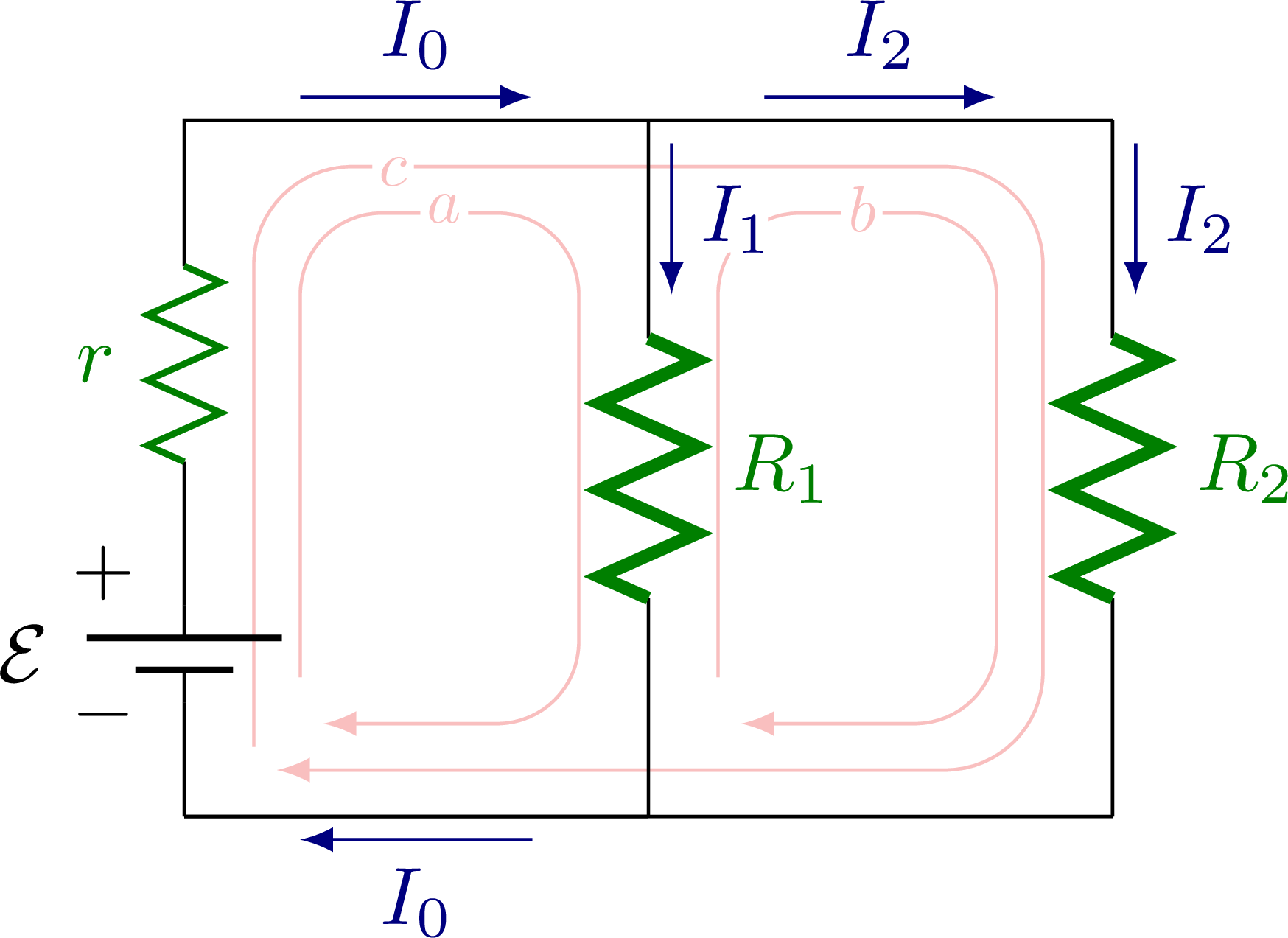
% RESISTOR in parallel - R1, R2
\begin{tikzpicture}
\draw[rounded corners=12,loop] (0.3,0.3) |- (3.7,2.8) |- (0.4,0.2);
\draw[rounded corners=10,loop] (0.5,0.6) |- (1.7,2.6) |- (0.6,0.4);
\draw[rounded corners=10,loop] (2.3,0.6) |- (3.5,2.6) |- (2.4,0.4);
\draw (0,0) to[EMF] (0,1.4)
to[internal R] (0,2.5)
-- (0,3) coordinate (I0) --++ (2,0) coordinate (I1)
to[thick R,l=$R_1$] (2,0) coordinate (IF) -- (0,0);
\draw (2,3) --++ (2,0) coordinate (I2)
to[thick R,l=$R_2$] (4,0) -- (0,0);
\node at (-0.35,0.44) {$-$};
\node at (-0.35,1.05) {$+$};
\draw[->,Icol] (I0)++(0.5, 0.1) --++ (1,0) node[midway,above] {$I_0$};
\draw[->,Icol] (I1)++(0.1,-0.1) --++ (0,-0.65) node[midway,right] {\contour{white}{$I_1$}};
\draw[->,Icol] (I1)++(0.5, 0.1) --++ (1,0) node[midway,above] {$I_2$};
\draw[->,Icol] (I2)++(0.1,-0.1) --++ (0,-0.65) node[midway,right] {$I_2$};
\draw[->,Icol] (IF)++(-0.5,-0.1) --++ (-1,0) node[midway,below] {$I_0$};
\node[loop label] at (0.90,2.78) {$c$};
\node[loop label] at (1.12,2.62) {$a$};
\node[loop label] at (2.92,2.62) {$b$};
\end{tikzpicture}
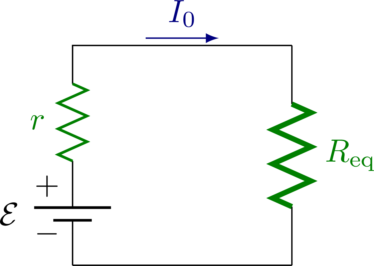
% RESISTOR in parallel - R12
\begin{tikzpicture}[scale=0.8]
\draw (0,0) to[EMF] (0,1.4)
to[internal R] (0,2.5) -- (0,3) coordinate (I0) --++ (3,0)
to[thick R,l=$R_\mathrm{eq}$] (3,0) -- (0,0); %R_{12}
\node at (-0.35,0.43) {$-$};
\node at (-0.35,1.08) {$+$};
\draw[->,Icol] (I0)++(1.0, 0.1) --++ (1,0) node[midway,above] {$I_0$};
\end{tikzpicture}
% RESISTOR in parallel - R12r
\begin{tikzpicture}[scale=0.7]
\draw (0,0) to[EMF] (0,3) --++ (3,0)
to[thick R,l=$R$] (3,0) -- (0,0); %_{12r}
\node at (-0.35,1.15) {$-$};
\node at (-0.35,1.90) {$+$};
\draw[->,Icol] (I0)++(1.0, 0.1) --++ (1,0) node[midway,above] {$I_0$};
\end{tikzpicture}
\end{document}
Click to download: electric_circuit_resistor.tex • electric_circuit_resistor.pdf
Open in Overleaf: electric_circuit_resistor.tex


")
