")


General Information
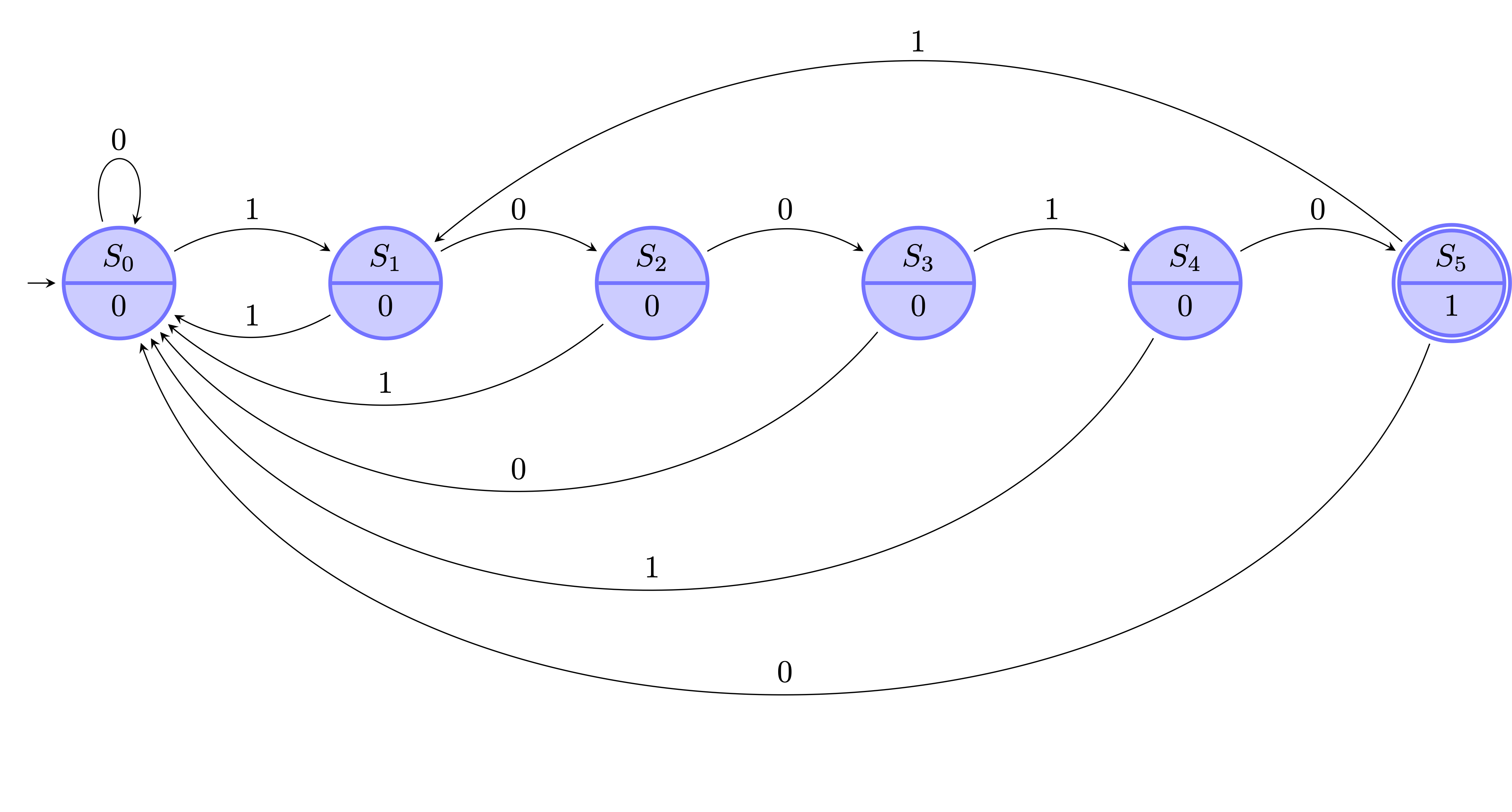
Moore finite state machine that recognizes the word 10010. Over the arrows is the input that causes the transition. Also, the states of the FSM are drawn blue with the corresponding name and output inside of them. When the output is 1 then the FSM has recognized the sequence 10010.
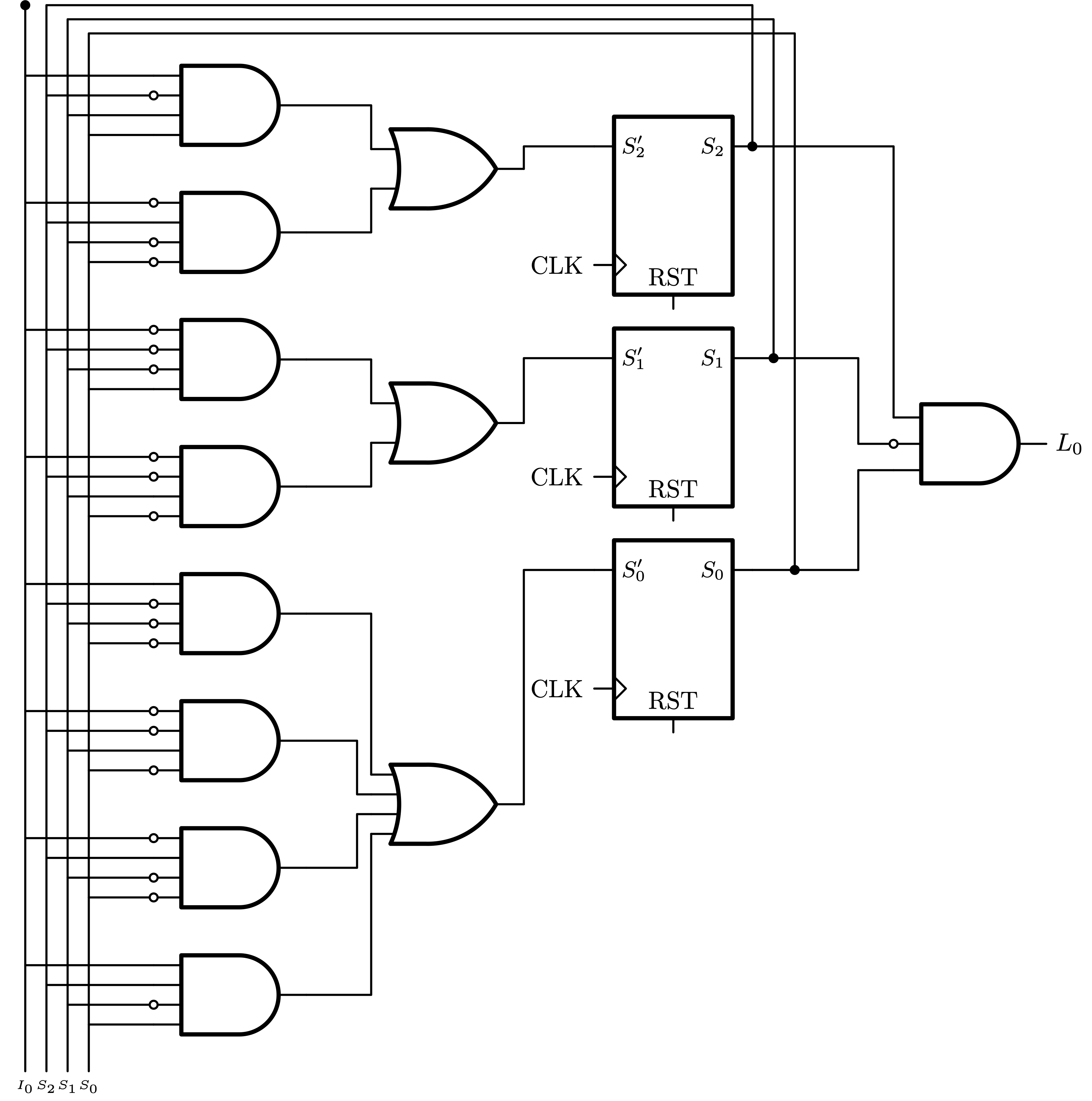
The second image depicts the circuit that implements the FSM described in the first one.
Schematic
\documentclass{standalone}

\usepackage{tikz}
\usetikzlibrary{automata, positioning, arrows, calc}

\tikzset{
	->,  % makes the edges directed
	>=stealth, % makes the arrow heads bold
	shorten >=2pt, shorten <=2pt, % shorten the arrow
	node distance=3cm, % specifies the minimum distance between two nodes. Change if n
	every state/.style={draw=blue!55,very thick,fill=blue!20}, % sets the properties for each ’state’ n
	initial text=$ $, % sets the text that appears on the start arrow
 }

\begin{document}
	\begin{tikzpicture}
		\node[state with output, initial] (s0) {$S_0$ \nodepart{lower} $0$};
		\node[state with output, right of=s0] (s1) {$S_1$ \nodepart{lower} $0$};
		\node[state with output, right of=s1] (s2) {$S_2$ \nodepart{lower} $0$};
		\node[state with output, right of=s2] (s3) {$S_3$ \nodepart{lower} $0$};
		\node[state with output, right of=s3] (s4) {$S_4$ \nodepart{lower} $0$};
		\node[state with output, accepting, right of=s4] (s5) {$S_5$ \nodepart{lower} $1$};

		\draw (s0) edge[loop above] node{$0$} (s0)
			  (s0) edge[bend left] node[above]{$1$} (s1)
			  %
			  (s1) edge[bend left] node[above]{$0$} (s2)
			  (s1) edge[bend left] node[above]{$1$} (s0)
			  %
			  (s2) edge[bend left] node[above]{$0$} (s3)
			  (s2) edge[bend left=40] node[above]{$1$} (s0)
			  %
			  (s3) edge[bend left=50] node[above]{$0$} (s0)
			  (s3) edge[bend left] node[above]{$1$} (s4)
			  %
			  (s4) edge[bend left] node[above]{$0$} (s5)
			  (s4) edge[bend left=60] node[above]{$1$} (s0)
			  %
			  (s5) edge[bend right=40] node[above]{$1$} (s1)
			  (s5) edge[bend left=70] node[above]{$0$} (s0)
		;
	\end{tikzpicture}
\end{document}
Circuitc
\documentclass{standalone}

% Tikz
\usepackage{tikz}
\usetikzlibrary{arrows,shapes.gates.logic.US,shapes.gates.logic.IEC,calc}

% Notation
\usepackage{amsmath, siunitx}

% Tikz Library
\usetikzlibrary{calc}
\tikzset{every picture/.style={line width=0.3mm}}

% Circuitikz
\usepackage[european,straightvoltages,americanresistor]{circuitikz}
\ctikzset{logic ports=ieee}

% Custom
\tikzset{sr-ff0/.style={flipflop D, flipflop def={t1=$S'_0$, t4=, t6=$S_0$}}}
\tikzset{sr-ff1/.style={flipflop D, flipflop def={t1=$S'_1$, t4=, t6=$S_1$}}}
\tikzset{sr-ff2/.style={flipflop D, flipflop def={t1=$S'_2$, t4=, t6=$S_2$}}}

\begin{document}

\tikzstyle{branch}=[fill, shape=circle, minimum size=3pt, inner sep=0pt]

	\begin{circuitikz}[line cap=round, line join =round]

		% States
		\node[sr-ff0] (s0) at (0,0) {};
		\node[sr-ff1, yshift=3cm] (s1) at (s0) {};
		\node[sr-ff2, yshift=3cm] (s2) at (s1) {};

		\draw (s2.bdown) -- +(0,-0.2)
		      (s1.bdown) -- +(0,-0.2)
		      (s0.bdown) -- +(0,-0.2);


		% Input
		\coordinate (end) at ($(s0.bdown) + (0,-5)$);
		\draw ($(s2.pin 6)+(0,0)$) to[short, *-] ++(0,2)
			  			 -- ++(-10,0) coordinate (rel_2)
			  			 -- (rel_2|-end) node[below] (ss2) {\tiny$S_2$}
		;
		\draw ($(s1.pin 6)+(0.3,0)$) to[short, *-] ++(0,4.8)
			  			 -- ++(-10,0) coordinate (rel_1)
			  			 -- (rel_1|-end) node[below] (ss1) {\tiny$S_1$}
		;
		\draw ($(s0.pin 6)+(0.6,0)$) to[short, *-] ++(0,7.6)
			  			 -- ++(-10,0) coordinate (rel_0)
			  			 -- (rel_0|-end) node[below] (ss0) {\tiny$S_0$}
		;
		\node (i0) at ($(ss2)+(-0.3,0)$) {\tiny$I_0$};
		\draw (i0) to[short, -*] (rel_2-|i0);
		%%%%% And %%%%%
		\foreach \i in {0,1,...,7} {
			\node[and port, number inputs=4] (and_s\i) at ($(ss0) + (2,1.3+\i*1.8)$) {};
		}
		%%%%% S0 %%%%%
		\draw (ss0|-and_s0.in 4) -- (and_s0.in 4)
			  (ss1|-and_s0.in 3) to[short, -o] (and_s0.in 3)
			  (ss2|-and_s0.in 2) -- (and_s0.in 2)
			  (i0|-and_s0.in 1) -- (and_s0.in 1)
		;
		\draw (ss0|-and_s1.in 4) to[short, -o] (and_s1.in 4)
			  (ss1|-and_s1.in 3) to[short, -o] (and_s1.in 3)
			  (ss2|-and_s1.in 2) -- (and_s1.in 2)
			  (i0|-and_s1.in 1) to[short, -o] (and_s1.in 1)
		;
		\draw (ss0|-and_s2.in 4) to[short, -o] (and_s2.in 4)
			  (ss1|-and_s2.in 3) -- (and_s2.in 3)
			  (ss2|-and_s2.in 2) to[short, -o] (and_s2.in 2)
			  (i0|-and_s2.in 1) to[short, -o] (and_s2.in 1)
		;
		\draw (ss0|-and_s3.in 4) to[short, -o] (and_s3.in 4)
			  (ss1|-and_s3.in 3) to[short, -o] (and_s3.in 3)
			  (ss2|-and_s3.in 2) to[short, -o] (and_s3.in 2)
			  (i0|-and_s3.in 1) -- (and_s3.in 1)
		;
		%%%%%
		\node [or port, number inputs=4] (or_s0) at ($(and_s1.out)!0.5!(and_s2.out) + (2,0)$) {};
		\draw (and_s0.out) -| (or_s0.in 4)
			  (and_s1.out) -| ($(or_s0.in 3)+(-0.2,0)$) -- (or_s0.in 3)
			  (and_s2.out) -| ($(or_s0.in 2)+(-0.2,0)$) -- (or_s0.in 2)
			  (and_s3.out) -| (or_s0.in 1)
		;
		\draw (or_s0.out) |- (s0.pin 1);
		%%%%% S1 %%%%%
		\draw (ss0|-and_s4.in 4) to[short, -o] (and_s4.in 4)
			  (ss1|-and_s4.in 3) -- (and_s4.in 3)
			  (ss2|-and_s4.in 2) to[short, -o] (and_s4.in 2)
			  (i0|-and_s4.in 1) to[short, -o] (and_s4.in 1)
		;
		\draw (ss0|-and_s5.in 4) -- (and_s5.in 4)
			  (ss1|-and_s5.in 3) to[short, -o] (and_s5.in 3)
			  (ss2|-and_s5.in 2) to[short, -o] (and_s5.in 2)
			  (i0|-and_s5.in 1) to[short, -o] (and_s5.in 1)
		;
		\node [or port, number inputs=2] (or_s1) at ($(and_s4.out)!0.5!(and_s5.out) + (2,0)$) {};
		\draw (and_s4.out) -| (or_s1.in 2)
			  (and_s5.out) -| (or_s1.in 1)
		;
		\draw (or_s1.out) |- (s1.pin 1);
		%%%%% S2 %%%%%
		\draw (ss0|-and_s6.in 4) to[short, -o] (and_s6.in 4)
			  (ss1|-and_s6.in 3) to[short, -o] (and_s6.in 3)
			  (ss2|-and_s6.in 2) -- (and_s6.in 2)
			  (i0|-and_s6.in 1) to[short, -o] (and_s6.in 1)
		;
		\draw (ss0|-and_s7.in 4) -- (and_s7.in 4)
			  (ss1|-and_s7.in 3) -- (and_s7.in 3)
			  (ss2|-and_s7.in 2) to[short, -o] (and_s7.in 2)
			  (i0|-and_s7.in 1) -- (and_s7.in 1)
		;
		\node [or port, number inputs=2] (or_s2) at ($(and_s6.out)!0.5!(and_s7.out) + (2,0)$) {};
		\draw (and_s6.out) -| (or_s2.in 2)
			  (and_s7.out) -| (or_s2.in 1)
		;
		\draw (or_s2.out) |- (s2.pin 1);

		% Output
		\draw (s2.pin 6) -- ++(2,0) coordinate (s2')
					     -- (s1.center-|s2') node[and port, anchor=in 1, number inputs = 3] (and_out) {}
			  (s1.pin 6) -- ++(1.5,0) coordinate (rel) -- (rel|-and_out.in 2)
			  			 to[short, -o] (and_out.in 2)
			  (s0.pin 6) -- ++(1.5,0) |- (and_out.in 3)
		;

		% Nodes
		\node[xshift=-15pt] at (s2.pin 3) {CLK};
		\node[xshift=-15pt] at (s1.pin 3) {CLK};
		\node[xshift=-15pt] at (s0.pin 3) {CLK};

		\node[above] at (s2.bdown) {RST};
		\node[above] at (s1.bdown) {RST};
		\node[above] at (s0.bdown) {RST};

		\node[right] at (and_out.out) {$L_0$};


%		% First State
%		\node[sr-ff] (q0) at (0,0) {};
%
%		% Cents
%		\node[circle, draw, shift={(0,10)}] (5cents) at (q0) {5 cents};
%		\draw[red] (5cents) -- ++(0,-7.8) coordinate (5cents_line) to[short,-*] +(44.7,0);
%
%		\node[circle, draw, shift={(2,0)}] (10cents) at (5cents) {10 cents};
%		\draw[blue] (10cents) -- ++(0,-5.2) coordinate (10cents_line) to[short,-*] +(42.7,0);
%
%		\node[circle, draw, shift={(2,0)}] (25cents) at (10cents) {25 cents};
%		\draw[orange] (25cents) -- ++(0,-3.6) coordinate (25cents_line) to[short,-*] +(40.7,0);
%
%		% Q0 State
%		\draw (q0.pin 1) -- +(-1,0) node [left] {\texttt{1}}
%			  (q0.pin 6) -- ++(1,0) node[and port, anchor=in 2] (and_q0) {}
%			  ($(and_q0.in 1|-5cents_line)$) to[short, *-] (and_q0.in 1);
%
%		\node[or port, rotate=180, number inputs=3, shift={(0,10)}] (or_q0_reset) at (q0) {};
%		\draw (or_q0_reset.out) -- ($(q0.pin 3|-or_q0_reset.out)$) -- (q0.pin 3);
%
%		% Q1 State
%		\draw (and_q0.out) -- ($(and_q0.out|-q0.pin 1)$) -- ++(1,0)
%			  node[sr-ff, anchor=pin 1] (q1) {}
%			  (q1.pin 6) to[short] ($(q1.pin 6|-or_q0_reset.in 3)$) to[short, *-] (or_q0_reset.in 3);
%
%		\draw (q1.pin 6) -- ++(1,0) node[and port, anchor=in 2] (and_q1_5) {}
%			  ($(and_q1_5.in 1|-5cents_line)$) to[short] (and_q1_5.in 1)
%			  %
%			  (q0.pin 6) to[short, *-] ($(5cents_line-|q0.pin 6) + (0,0.5)$)
%			  coordinate (q0_line) to[short,*-] ($(and_q1_5.in 1|-q0_line)$)
%			  node[and port, anchor=in 2] (and_q1_10) {}
%			  %
%			  ($(and_q1_10.in 1|-10cents_line)$) to[short, *-] (and_q1_10.in 1)
%			  (and_q1_5.out) -- ++(1,0) node[or port, anchor=in 2] (or_q1) {}
%			  (and_q1_10.out) -| (or_q1.in 1);
%
%		\node[or port, rotate=180, shift={(0,8)}] (or_q1_reset) at (q1) {};
%		\draw (or_q1_reset.out) -- ($(q1.pin 3|-or_q1_reset.out)$) -- (q1.pin 3);
%
%		% Q2 State
%		\draw (or_q1.out) -- ($(or_q1.out|-q1.pin 1)$) -- ++(1,0)
%			  node[sr-ff, anchor=pin 1] (q2) {}
%   			  (q2.pin 6) to[short, *-] ($(q2.pin 6|-or_q1_reset.in 2)$) to[short, *-] (or_q1_reset.in 2)
%   			  (q2.pin 6) |- (or_q0_reset.in 2);
%
%		\draw (q2.pin 6) -- ++(1,0) node[and port, anchor=in 2] (and_q2_5) {}
%			  ($(and_q2_5.in 1|-5cents_line)$) to[short, *-] (and_q2_5.in 1)
%			  %
%			  (q1.pin 6) to[short, *-] ($(5cents_line-|q1.pin 6) + (0,1.5)$)
%			  coordinate (q0_line) to ($(and_q2_5.in 1|-q0_line)$)
%			  node[and port, anchor=in 2] (and_q2_10) {}
%			  %
%			  ($(and_q2_10.in 1|-10cents_line)$) to[short, *-] (and_q2_10.in 1)
%			  (and_q2_5.out) -- ++(1,0) node[or port, anchor=in 2] (or_q2) {}
%			  (and_q2_10.out) -| (or_q2.in 1);
%
%		\node[or port, rotate=180, shift={(0,6)}] (or_q2_reset) at (q2) {};
%		\draw (or_q2_reset.out) -- ($(q2.pin 3|-or_q2_reset.out)$) -- (q2.pin 3);
%
%		% Q3 State
%		\draw (or_q2.out) -- ($(or_q2.out|-q2.pin 1)$) -- ++(1,0)
%		  node[sr-ff, anchor=pin 1] (q3) {}
%		  (q3.pin 6) to[short, *-] ($(q3.pin 6|-or_q2_reset.in 2)$) to[short, *-] (or_q2_reset.in 2)
%		  (q3.pin 6) |- (or_q1_reset.in 1);
%
%		\draw (q3.pin 6) -- ++(1,0) node[and port, anchor=in 2] (and_q3_5) {}
%			  ($(and_q3_5.in 1|-5cents_line)$) to[short, *-] (and_q3_5.in 1)
%			  %
%			  (q2.pin 6) to[short, *-] ($(5cents_line-|q2.pin 6) + (0,0.5)$)
%			  coordinate (q0_line) to ($(and_q3_5.in 1|-q0_line)$)
%			  node[and port, anchor=in 2] (and_q3_10) {}
%			  %
%			  ($(and_q3_10.in 1|-10cents_line)$) to[short, *-] (and_q3_10.in 1)
%			  (and_q3_5.out) -- ++(1,0) node[or port, anchor=in 2] (or_q3) {}
%			  (and_q3_10.out) -| (or_q3.in 1);
%
%		\node[or port, rotate=180, shift={(0,4)}] (or_q3_reset) at (q3) {};
%		\draw (or_q3_reset.out) -- ($(q3.pin 3|-or_q3_reset.out)$) -- (q3.pin 3);
%
%		% Q4 State
%		\draw (or_q3.out) -- ($(or_q3.out|-q3.pin 1)$) -- ++(1,0)
%		  node[sr-ff, anchor=pin 1] (q4) {}
%		  (q4.pin 6) to[short, *-] ($(q4.pin 6|-or_q3_reset.in 2)$) to[short, *-] (or_q3_reset.in 2)
%		  (q4.pin 6) |- (or_q2_reset.in 1);
%
%		\draw (q4.pin 6) -- ++(1,0) node[and port, anchor=in 2] (and_q4_5) {}
%			  ($(and_q4_5.in 1|-5cents_line)$) to[short, *-] (and_q4_5.in 1)
%			  %
%			  (q3.pin 6) to[short, *-] ($(5cents_line-|q3.pin 6) + (0,1.5)$)
%			  coordinate (q0_line) to ($(and_q4_5.in 1|-q0_line)$)
%			  node[and port, anchor=in 2] (and_q4_10) {}
%			  ($(and_q4_10.in 1|-10cents_line)$) to[short, *-] (and_q4_10.in 1)
%			  %
%			  (q0.pin 6) to[short, *-] ($(10cents_line-|q0.pin 6) + (0,0.5)$)
%			  coordinate (q1_line) to ($(and_q4_5.in 1|-q1_line)$)
%			  node[and port, anchor=in 2] (and_q4_25) {}
%			  ($(and_q4_25.in 1|-25cents_line)$) to[short, *-] (and_q4_25.in 1)
%			  %
%			  (and_q4_5.out) -- ++(1,0) node[or port, anchor=in 3, number inputs=3] (or_q4) {}
%			  (and_q4_10.out) -- ($(and_q4_10.out|-or_q4.in 2)$) -- (or_q4.in 2)
%			  (and_q4_25.out) -- ++(0.6,0) coordinate (and_q4_25_line) --
%			  ($(and_q4_25_line|-or_q4.in 1)$) -- (or_q4.in 1);
%
%		% Q5 State
%		\draw (or_q4.out) -- ($(or_q4.out|-q4.pin 1)$) -- ++(1,0)
%		  node[sr-ff, anchor=pin 1] (q5) {}
%		  (q5.pin 6) to[short, -*] ($(q5.pin 6|-or_q3_reset.in 2) + (0,1.5)$) -| (q4.pin 3)
%		  (q5.pin 6) to[short, -*] ($(q5.pin 6|-or_q3_reset.in 1)$) -| (or_q3_reset.in 1)
%		  (q5.pin 6) -- ($(q5.pin 6|-or_q0_reset.in 1)$) to[short] (or_q0_reset.in 1)
%		  (q5.pin 3) -- +(0,-0.4) node[ground] {}
%		  (q5.pin 6) to[short] +(1,0);
%
%		% Nodes
%		\node[circle, draw, fill=black!20] at (q0) {q0};
%		\node[circle, draw, fill=black!20] at (q1) {q1};
%		\node[circle, draw, fill=black!20] at (q2) {q2};
%		\node[circle, draw, fill=black!20] at (q3) {q3};
%		\node[circle, draw, fill=black!20] at (q4) {q4};
%		\node[circle, draw, fill=black!20] at (q5) {q5};
%
	\end{circuitikz}
\end{document}