")


Plate and spherical capacitors, as well as dielectric medium.
Plate capacitor (3D):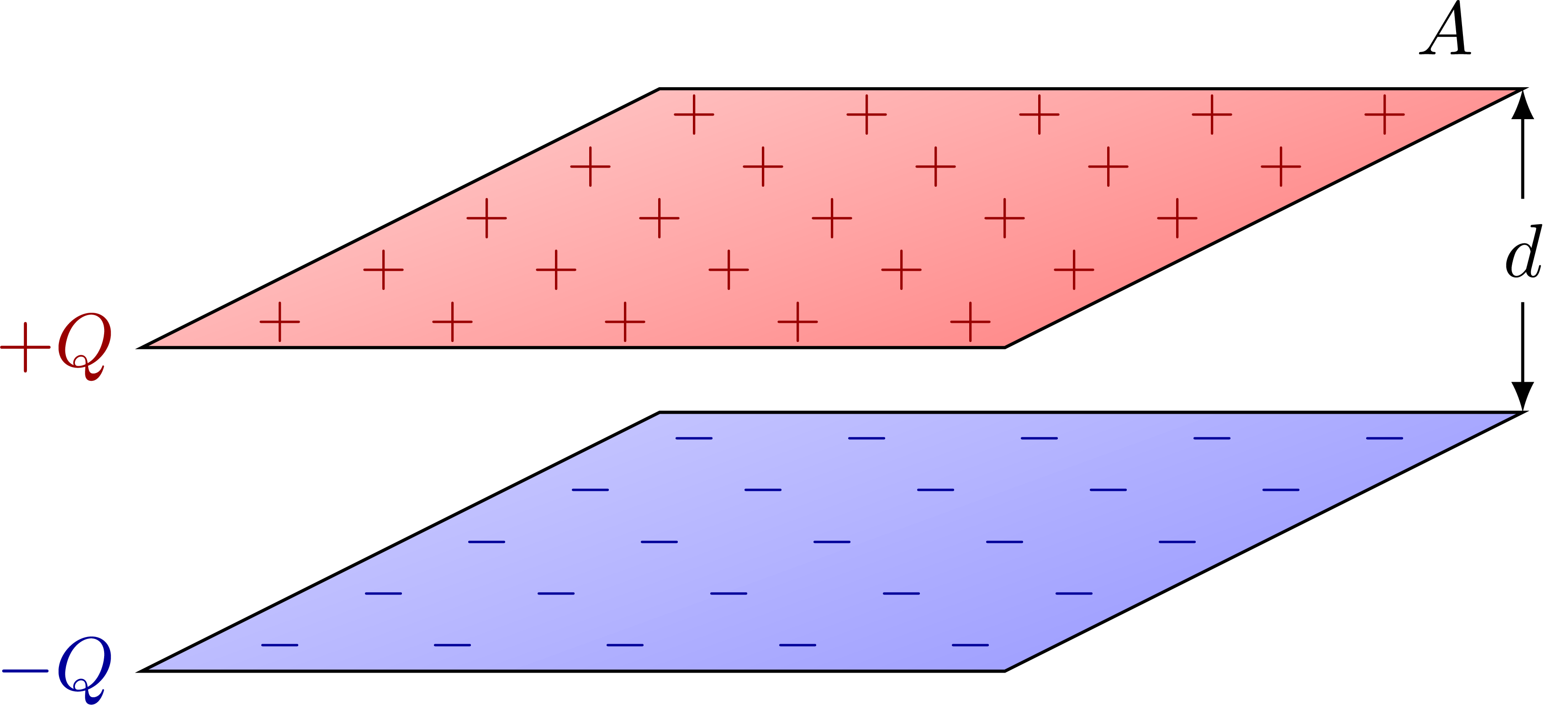 Plate capacitor with field lines:
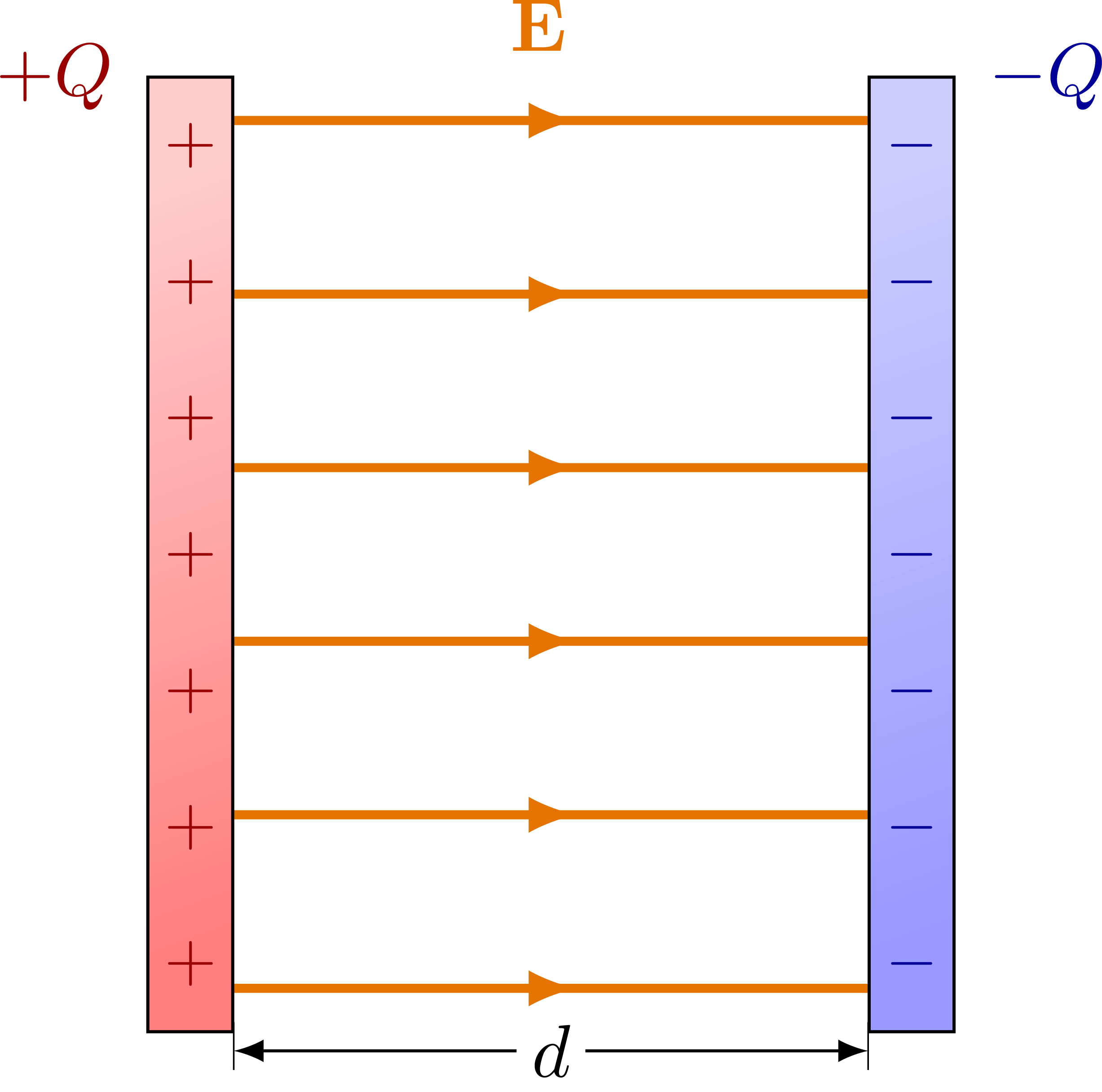 Plate capacitor with external field lines:
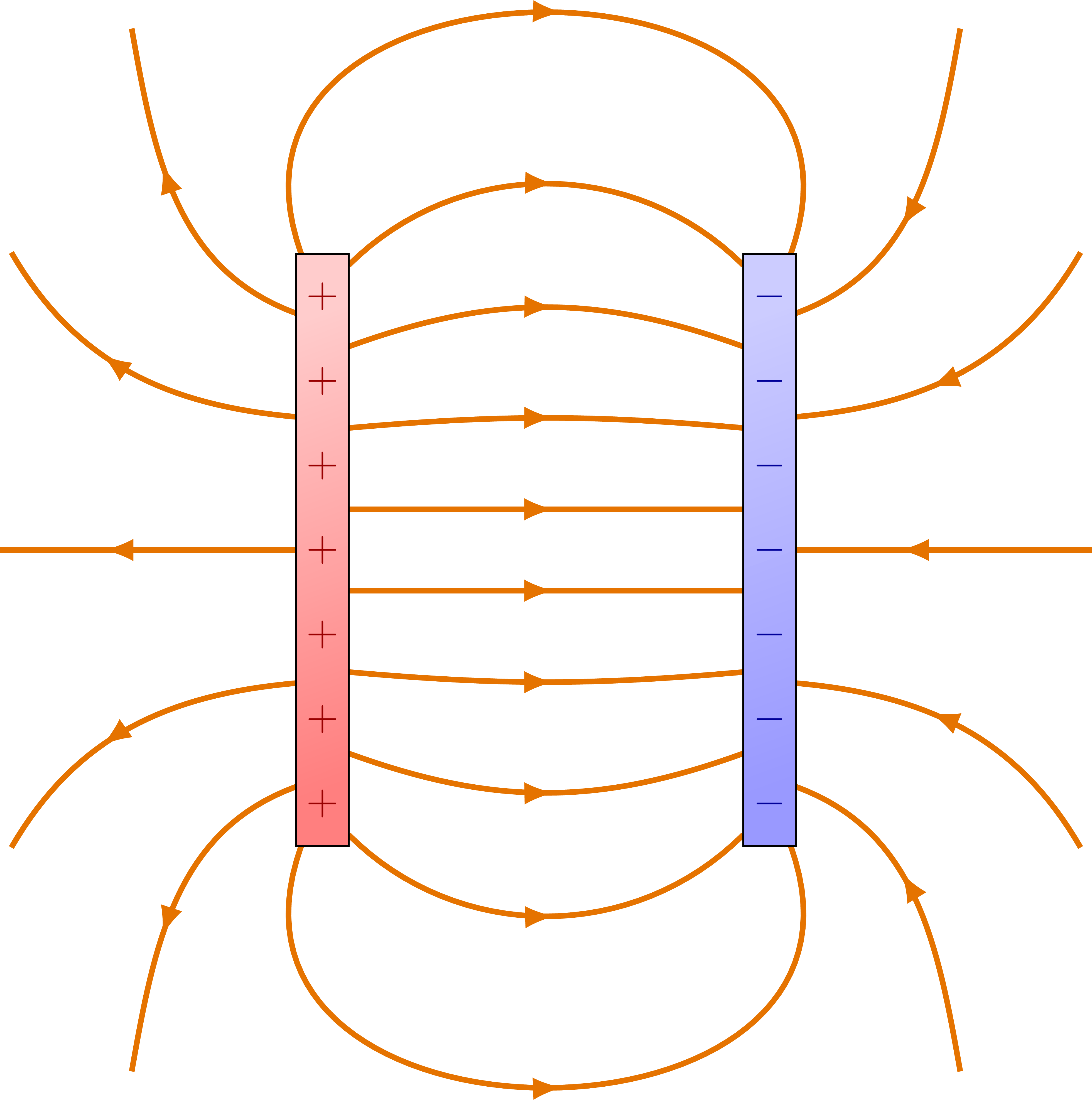 Dielectric medium with unpolarized dipoles:
 Plate capacitor with dielectric medium with polarized dipoles:
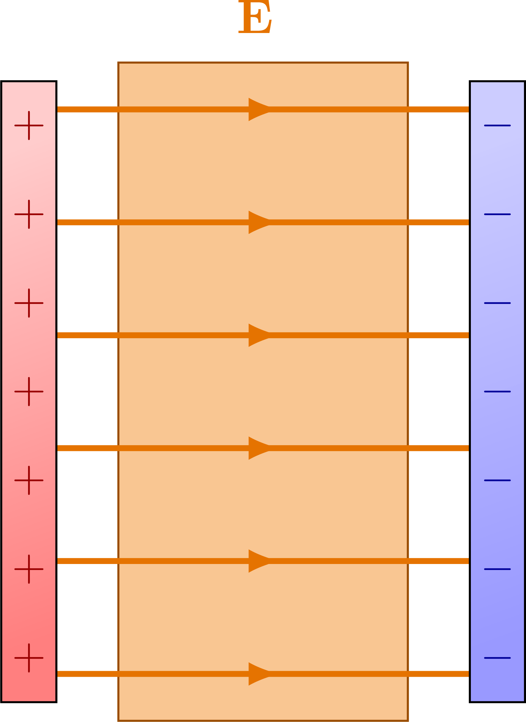 Dielectric force:
 Spherical capacitors:
 Charged capacitors in a circuit:
Edit and compile if you like:
% Author: Izaak Neutelings (February 2020)

\documentclass[border=3pt,tikz]{standalone}
\usepackage{amsmath} % for \dfrac
\usepackage{bm}
\usepackage{physics}
\usepackage{tikz,pgfplots}
\usetikzlibrary{angles,quotes} % for pic (angle labels)
\usetikzlibrary{decorations.markings}
\usetikzlibrary{calc}
\usetikzlibrary{shapes,intersections} % for path name
\tikzset{>=latex} % for LaTeX arrow head

\usepackage{xcolor}
\colorlet{Ecol}{orange!90!black}
\colorlet{EcolFL}{orange!90!black}
\colorlet{veccol}{green!45!black}
\colorlet{EFcol}{red!60!black}
\colorlet{pluscol}{red!60!black}
\colorlet{minuscol}{blue!60!black}
\tikzstyle{anode}=[top color=red!20,bottom color=red!50,shading angle=20]
\tikzstyle{cathode}=[top color=blue!20,bottom color=blue!40,shading angle=20]
\tikzstyle{charge+}=[very thin,top color=red!80,bottom color=red!80!black,shading angle=-5]
\tikzstyle{charge-}=[very thin,top color=blue!50,bottom color=blue!70!white!90!black,shading angle=10]
\tikzstyle{vector}=[->,thick,veccol]
\tikzstyle{normalvec}=[->,thick,blue!80!black!80]
\tikzstyle{Cstyle}=[very thick,orange!90!black]
\tikzstyle{EField}=[->,thick,Ecol]
\tikzstyle{EField dashed}=[dashed,Ecol,line width=0.6]
\tikzset{
  EFieldLine/.style={thick,EcolFL,decoration={markings,
                     mark=at position #1 with {\arrow{latex}}},
                     postaction={decorate}},
  EFieldLine/.default=0.5}
\tikzstyle{measure}=[fill=white,midway,outer sep=2]

\def\dpa{0.28}
\def\dba{0.14}
\def\dipole#1#2{
  \begin{scope}[shift={(#1)},rotate=#2]
    \draw[charge-] (-\dpa,0) to[out=90,in=180] (0,\dba) -- (0,-\dba) to[out=180,in=-90] cycle;
    \draw[charge+] ( \dpa,0) to[out=90,in=  0] (0,\dba) -- (0,-\dba) to[out=  0,in=-90] cycle;
    \node[scale=0.7] at (-\dpa/2,0) {$-$};
    \node[scale=0.7] at ( \dpa/2,0) {$+$};
  \end{scope}
}

\begin{document}


% CAPACITOR 3D
\begin{tikzpicture}[x={(1cm,0)},y={(0.6cm,0.3cm)},z={(0,1cm)}]
  \def\H{1.5}
  \def\W{4}
  \def\L{4}
  \def\Nx{5}
  \def\Ny{5}
  \draw[cathode]
    (0,0,0) --++ (\L,0,0) --++ (0,\W,0) --++ (-\L,0,0) -- cycle;
  \draw[anode]
    (0,0,\H) --++ (\L,0,0) --++ (0,\W,0) --++ (-\L,0,0) -- cycle;
  \foreach \i [evaluate={\x=(\i-0.5)*\L/\Nx;}] in {1,...,\Nx}{
    \foreach \j [evaluate={\y=(\j-0.5)*\W/\Ny;}] in {1,...,\Ny}{
      \node[minuscol,scale=0.8] at (\x,\y,0) {$-$};
      \node[pluscol,scale=0.8] at (\x,\y,\H) {$+$};
    }
  }
  \node[minuscol,left] at (0,0,0) {$-Q$};
  \node[pluscol,left] at (0,0,\H) {$+Q$};
  \node[left=2,above left=1] at (\L,\W,\H) {$A$};
  \draw[<->] (\L,\W,0) -- (\L,\W,\H) node[measure] {$d$};
\end{tikzpicture}


% CAPACITOR 2D
\def\H{4.5}
\def\W{3.0}
\def\w{0.4}
\def\a{0.15*\W}
\def\NE{6}
\def\NQ{7}
\begin{tikzpicture}

  % ELECTRIC FIELD
  \foreach \i [evaluate={\y=(\i-0.75)*\H/(\NE-0.5);}] in {1,...,\NE}{
    \draw[EFieldLine={0.54},very thick] (0,\y) --++ (\W,0);
  }

  % PLATES
  \draw[anode]
    (0,0) rectangle++ (-\w,\H);
  \draw[cathode]
    (\W,0) rectangle++ (\w,\H);
  \foreach \i [evaluate={\y=(\i-0.5)*\H/\NQ;}] in {1,...,\NQ}{
    \node[pluscol,scale=0.9] at (-\w/2,\y) {$+$};
    \node[minuscol,scale=0.9] at (\W+\w/2,\y) {$-$};
  }
  \node[Ecol,above] at (0.48*\W,1.0*\H) {$\vb{E}$};
  \node[pluscol] at (-2.1*\w,\H) {$+Q$};
  \node[minuscol] at (\W+2.1*\w,\H) {$-Q$};
  \draw[very thin] (0.005,-0.04*\H) --++ (0,0.05*\H);
  \draw[very thin] (\W-0.005,-0.04*\H) --++ (0,0.05*\H);
  \draw[<->] (0.005,-0.02*\H) --++ (\W-0.01,0) node[measure,inner sep=2] {$d$};

\end{tikzpicture}


% CAPACITOR 2D - realistic
\begin{tikzpicture}
  \def\NE{4}
  \def\R{2.5}

  % ELECTRIC FIELD
  \foreach \i [evaluate={\y=0.55*(\i-0.5)*\H/\NE; \ang=(\i-1)*(\i-1)*20/\NE;}] in {1,...,\NE}{
    \draw[EFieldLine={0.52},very thick] (0,\H/2+\y) to[out=\ang,in=180-\ang]++ (\W,0);
    \draw[EFieldLine={0.52},very thick] (0,\H/2-\y) to[out=-\ang,in=180+\ang]++ (\W,0);
  }
  \foreach \y/\ang/\out/\in in {0.8/60/20/-100,0.45/30/5/-120}{
    \draw[EFieldLine={0.6},very thick] (\W+\w,{(1+\y)*\H/2})++(\ang:\R) to[out=\in,in=\out]++ (\ang:-\R);
    \draw[EFieldLine={0.6},very thick] (\W+\w,{(1-\y)*\H/2})++(-\ang:\R) to[out=-\in,in=-\out]++ (-\ang:-\R);
    \draw[EFieldLine={0.6},very thick] (-\w,{(1+\y)*\H/2}) to[out=180-\out,in=180-\in]++ (-\ang:-\R);
    \draw[EFieldLine={0.6},very thick] (-\w,{(1-\y)*\H/2}) to[out=180+\out,in=180+\in]++ (+\ang:-\R);
  }
  \draw[EFieldLine={0.52},very thick] (-0.9*\w,\H) to[out=110,in=70,looseness=1.8] (\W+0.9*\w,\H);
  \draw[EFieldLine={0.52},very thick] (-0.9*\w,0) to[out=-110,in=-70,looseness=1.8] (\W+0.9*\w,0);
  \draw[EFieldLine={0.65},very thick] (\W+\w+0.9*\R,\H/2) --++ (-0.9*\R,0);
  \draw[EFieldLine={0.65},very thick] (-\w,\H/2) --++ (-0.9*\R,0);

  % PLATES
  \draw[anode]
    (0,0) rectangle++ (-\w,\H);
  \draw[cathode]
    (\W,0) rectangle++ (\w,\H);
  \foreach \i [evaluate={\y=(\i-0.5)*\H/\NQ;}] in {1,...,\NQ}{
    \node[pluscol,scale=0.9] at (-\w/2,\y) {$+$};
    \node[minuscol,scale=0.9] at (\W+\w/2,\y) {$-$};
  }
  %\node[Ecol,above] at (0.48*\W,1.0*\H) {$\vb{E}$};

\end{tikzpicture}


% DIPOLES without capacitors
\begin{tikzpicture}

  % DIELECTRIC
  \draw[orange!60!black,fill=orange!80!brown!5]
    (\a,-0.03*\H) rectangle (\W-\a,1.03*\H);

  % DIPOLE
  \dipole{0.26*\W,0.1*\H}{320}
  \dipole{0.26*\W,0.3*\H}{220}
  \dipole{0.26*\W,0.5*\H}{30}
  \dipole{0.26*\W,0.7*\H}{260}
  \dipole{0.26*\W,0.9*\H}{70}
  \dipole{0.50*\W,0.1*\H}{30}
  \dipole{0.50*\W,0.3*\H}{160}
  \dipole{0.50*\W,0.5*\H}{80}
  \dipole{0.50*\W,0.7*\H}{150}
  \dipole{0.50*\W,0.9*\H}{110}
  \dipole{0.74*\W,0.1*\H}{100}
  \dipole{0.74*\W,0.3*\H}{220}
  \dipole{0.74*\W,0.5*\H}{160}
  \dipole{0.74*\W,0.7*\H}{30}
  \dipole{0.74*\W,0.9*\H}{340}

\end{tikzpicture}


% CAPACITOR 2D - dipole
\begin{tikzpicture}

  % DIELECTRIC
  \draw[orange!60!black,fill=orange!80!brown!5]
    (\a,-0.03*\H) rectangle (\W-\a,1.03*\H);

  % ELECTRIC FIELD
  \foreach \i [evaluate={\y=(\i-0.75)*\H/(\NE-0.5);}] in {1,...,\NE}{
    \draw[EFieldLine={0.54},very thick] (0,\y) --++ (\W,0);
  }

  % PLATES
  \draw[anode]
    (0,0) rectangle++ (-\w,\H);
  \draw[cathode]
    (\W,0) rectangle++ (\w,\H);
  \foreach \i [evaluate={\y=(\i-0.5)*\H/\NQ;}] in {1,...,\NQ}{
    \node[pluscol,scale=0.9] at (-\w/2,\y) {$+$};
    \node[minuscol,scale=0.9] at (\W+\w/2,\y) {$-$};
  }
  \node[Ecol,above] at (0.48*\W,1.05*\H) {$\vb{E}$};
  \node[above,scale=0.95,minuscol] at (   1.3*\a,1.02*\H) {$-\sigma_\mathrm{b}$};
  \node[above,scale=0.95,pluscol]  at (\W-1.3*\a,1.02*\H) {$+\sigma_\mathrm{b}$};
  \node[above,scale=0.95,pluscol]  at (  -0.5*\w,0.99*\H) {$+\sigma_\mathrm{f}$};
  \node[above,scale=0.95,minuscol] at (\W+0.5*\w,0.99*\H) {$-\sigma_\mathrm{f}$};

  % DIPOLE
  \dipole{0.26*\W,0.1*\H}{0}
  \dipole{0.26*\W,0.3*\H}{0}
  \dipole{0.26*\W,0.5*\H}{0}
  \dipole{0.26*\W,0.7*\H}{0}
  \dipole{0.26*\W,0.9*\H}{0}
  \dipole{0.50*\W,0.1*\H}{0}
  \dipole{0.50*\W,0.3*\H}{0}
  \dipole{0.50*\W,0.5*\H}{0}
  \dipole{0.50*\W,0.7*\H}{0}
  \dipole{0.50*\W,0.9*\H}{0}
  \dipole{0.74*\W,0.1*\H}{0}
  \dipole{0.74*\W,0.3*\H}{0}
  \dipole{0.74*\W,0.5*\H}{0}
  \dipole{0.74*\W,0.7*\H}{0}
  \dipole{0.74*\W,0.9*\H}{0}

\end{tikzpicture}


% CAPACITOR 2D - dielectric
\begin{tikzpicture}

  % DIELECTRIC
  \draw[orange!60!black,fill=orange!80!brown!45]
    (\a,-0.03*\H) rectangle (\W-\a,1.03*\H);

  % ELECTRIC FIELD
  \foreach \i [evaluate={\y=(\i-0.75)*\H/(\NE-0.5);}] in {1,...,\NE}{
    \draw[EFieldLine={0.54},very thick] (0,\y) --++ (\W,0);
  }

  % PLATES
  \draw[anode]
    (0,0) rectangle++ (-\w,\H);
  \draw[cathode]
    (\W,0) rectangle++ (\w,\H);
  \foreach \i [evaluate={\y=(\i-0.5)*\H/\NQ;}] in {1,...,\NQ}{
    \node[pluscol,scale=0.9] at (-\w/2,\y) {$+$};
    \node[minuscol,scale=0.9] at (\W+\w/2,\y) {$-$};
  }
  \node[Ecol,above] at (0.48*\W,1.05*\H) {$\vb{E}$};

\end{tikzpicture}


% CAPACITOR 2D - dielectric force
\begin{tikzpicture}
  \def\H{6.4}
  \def\W{2.0}
  \def\w{0.4}
  \def\NE{5}
  \def\NQ{8}

  % DIELECTRIC
  \draw[orange!60!black,fill=orange!80!brown!45]
    (0.46*\H,\a) rectangle ++(\H,\W-2*\a);
  \foreach \i [evaluate={\x=0.46*\H+(\i-0.5)*\H/\NQ;}] in {1,...,\NQ}{
    \node[red!60!black,scale=0.9,below] at (\x,\W-\a) {$+$};
    \node[blue!60!black,scale=0.9,above] at (\x,\a) {$-$};
  }
  \draw[->,EFcol,very thick]
    (0.46*\H,\W/2) --++ (-0.15*\H,0) node[right=2,above=2] {$\vb{F}$};
  \draw[->,thick]
    (1.1*\H,-\w/2) --++ (0.2*\H,0) node[right=2] {$x$};

  % ELECTRIC FIELD
  \foreach \i [evaluate={\x=(\i-0.75)*\H/(\NE-0.5);}] in {1,...,\NE}{
    \draw[EFieldLine={0.57},very thick] (\x,0) --++ (0,\W);
  }

  % PLATES
  \draw[anode]
    (0,0) rectangle++ (\H,-\w);
  \draw[cathode]
    (0,\W) rectangle++ (\H,\w);
  \foreach \i [evaluate={\x=(\i-0.5)*\H/\NQ;}] in {1,...,\NQ}{
    \node[pluscol,scale=0.9] at (\x,-\w/2) {$+$};
    \node[minuscol,scale=0.9] at (\x,\W+\w/2) {$-$};
  }
  \node[Ecol] at (-0.01*\H,\W/2) {$\vb{E}$};

\end{tikzpicture}


% CAPACITOR 2D - circular
\begin{tikzpicture}
  \def\NE{10}
  \def\NQ{11}
  \def\Rin{0.8}
  \def\Rout{2.5}
  \def\a{0.3}

  % ELECTRIC FIELD
  \foreach \i [evaluate={\ang=\i*360/\NE;}] in {1,...,\NE}{
    \draw[EFieldLine={0.54},thick] (\ang:\Rin+\a) -- (\ang:\Rout);
  }

  % PLATES
  \draw[anode,even odd rule]
    (0,0) circle (\Rin) circle (\Rin+\a);
  \draw[cathode,even odd rule]
    (0,0) circle (\Rout) circle (\Rout+\a);
  \foreach \i [evaluate={\ang=\i*360/\NQ;}] in {1,...,\NQ}{
    \node[scale=0.9] at (\ang:\Rin+\a/2) {$+$};
    \node[scale=0.9] at (\ang:\Rout+\a/2) {$-$};
  }
  \node[pluscol,above] at (135:\Rin+1.3*\a) {$+Q$};
  \node[minuscol,above] at (135:\Rout+1.4*\a) {$-Q$};
  %\node[Ecol,above] at (0.48*\W,1.05*\H) {$\vb{E}$};
  \draw[->] (0,0) -- (15:\Rin) node[midway,below] {$r_a$};
  \draw[->] (0,0) -- (48:\Rout) node[midway,above=4] {$r_b$};

\end{tikzpicture}


% CAPACITOR
\begin{tikzpicture}
  \def\h{1.1}
  \def\l{1.6}
  \def\g{0.5}
  %\hnode[pluscol,above] at (135:\Rin+1.3*\l) {$+Q$};
  \draw[thick] (0,0) -- (\l,0) coordinate (C1L) node[midway,above=-1] {$V_a$};
  \draw[thick] (C1L)++(\g,0) coordinate (C1R) --++ (\l,0) coordinate (C2L) node[midway,above=-1] {$V_b$};
  \draw[thick] (C2L)++(\g,0) coordinate (C2R) --++ (\l,0) node[midway,above=-1] {$V_c$};
  \draw[Cstyle] (C1L)++(0,-\h/2) node[pluscol, above left=-2, scale=0.95] {$+Q$} --++ (0,\h) coordinate (C1LT);
  \draw[Cstyle] (C1R)++(0,-\h/2) node[minuscol,above right=-2,scale=0.95] {$-Q$} --++ (0,\h) coordinate (C1RT);
  \draw[Cstyle] (C2L)++(0,-\h/2) node[pluscol, above left=-2, scale=0.95] {$+Q$} --++ (0,\h) coordinate (C2LT);
  \draw[Cstyle] (C2R)++(0,-\h/2) node[minuscol,above right=-2,scale=0.95] {$-Q$} --++ (0,\h) coordinate (C2RT);
  \draw[<->] ($(C1LT)+(0,0.2*\h)$) -- ($(C1RT.90)+(0,0.2*\h)$) node[midway,above] {$V_1$};
  \draw[<->] ($(C2LT)+(0,0.2*\h)$) -- ($(C2RT.90)+(0,0.2*\h)$) node[midway,above] {$V_2$};
  \node[Ecol,below] at ($(C1L)+(\g/2,-\h/2)$) {$C_1$};
  \node[Ecol,below] at ($(C2L)+(\g/2,-\h/2)$) {$C_2$};
\end{tikzpicture}


\end{document}
Click to download: capacitors.tex • capacitors.pdf
Open in Overleaf: capacitors.tex


Hello,
Beautiful! Congratulations for all your figures!
Looking at the figure “Plate capacitor with external field lines”, the field lines on the right, on the right of the negatively charged plate have the wrong orientation. They should point towards the plate.
Hi Thomas, thank you for pointing that out! I fixed it. Cheers!