")


For an alternate, more accurate method with pstricks, please see this page.
Edit and compile if you like:
% Author: Izaak Neutelings (March 2020)
\documentclass[border=3pt,tikz]{standalone}
\usepackage{amsmath} % for \dfrac
\usepackage{bm}
\usepackage{tikz,pgfplots}
\tikzset{>=latex} % for LaTeX arrow head
\pgfplotsset{compat=1.13}
\usetikzlibrary{decorations.markings,intersections,calc}
\usepackage{ifthen}
\usepackage{xcolor}
\usepackage{auto-pst-pdf}
\usepackage{pst-magneticfield}
\usepackage[outline]{contour} % glow around text
\colorlet{Bcol}{violet!90}
\colorlet{BcolFL}{violet!90}
\tikzstyle{north}=[thick,top color=red!60,bottom color=red!90,shading angle=20]
\tikzstyle{south}=[thick,top color=blue!60,bottom color=blue!90,shading angle=20]
\contourlength{1.5pt}
\tikzset{
EFielLineArrow/.style args={#1,#2}{BcolFL,thick,decoration={markings,
mark=at position #1 with {\arrow[rotate=#2]{latex}}},
postaction={decorate}}
}
\makeatletter
\newcommand{\xy}[3]{% % FIND X, Y
\tikz@scan@one@point\pgfutil@firstofone#1\relax
\edef#2{\the\pgf@x}%
\edef#3{\the\pgf@y}%
}
\makeatother
\newcommand{\EFielLineArrow}[2]{ % ELECTRIC FIELD LINE ARROW
\pgfkeys{/pgf/fpu,/pgf/fpu/output format=fixed} % for calculation between -1*10^324 and +1*10^324
\pgfmathsetmacro{\x}{#1/28.45pt}
\pgfmathsetmacro{\y}{#2/28.45pt}
\pgfmathsetmacro{\U}{\Q*((\y+\a)^2+(\x)^2)^(3/2)}
\pgfmathsetmacro{\V}{-(\Q)*((\y-\a)^2+(\x)^2)^(3/2)}
\pgfkeys{/pgf/fpu=false}
\pgfmathparse{
atan2(((\y+\a)*\V + (\y-\a)*\U),((\x)*\V + (\x)*\U))
}
\edef\angle{\pgfmathresult}
\pgfmathsetmacro{\D}{int(1000*(\Q)*(\y+\a)/sqrt((\y+\a)^2+\x*\x) - 1000*(\Q)*(\y-\a)/sqrt((\y-\a)^2+\x*\x))/1000}
\draw[EFielLineArrow={0.5,\angle}] ({\xpt+(3pt)*cos(\angle)},{\ypt+(3pt)*sin(\angle)});
}
\newcommand{\EFieldLines}{ % ELECTRIC FIELD LINES
\message{^^JField lines {\Q} with contours range ^^J\range^^J}
% FIELD LINES
\draw[BcolFL,thick,name path=Elines] plot[id=plot, raw gnuplot, smooth]
function{
f(x,y) = \Q*(y+\a)/sqrt((y+\a)**2+x**2) - (\Q)*(y-\a)/sqrt((y-\a)**2+x**2);
set xrange [\xmin:\xmax];
set yrange [-\ymax:\ymax];
set view 0,0;
set isosample 800,800;
set cont base;
set cntrparam levels discrete \range;
unset surface;
splot f(x,y)
};
% ELLIPSE INTERSECTIONS
\path[name path=ellipse] (0,0) ellipse ({1.5*\R} and {\R+\a});
\path[name path=yline] (\xmin,0) -- (\xmax,0);
\message{Intersections...}
\path[name intersections={of=Elines and ellipse,total=\t}]
\pgfextra{\xdef\Nb{\t}};
\message{ found \Nb ^^J}
\foreach \i in {1,...,\Nb}{
\message{ \i}
\xy{(intersection-\i)}{\xpt}{\ypt}
\EFielLineArrow{\xpt}{\ypt}
\message{ (\D,\x,\y)^^J} %,\xpt,\ypt
}
\path[name intersections={of=Elines and yline,total=\t}]
\pgfextra{\xdef\Nb{\t}};
\message{ found \Nb ^^J}
\foreach \i in {1,...,\Nb}{
\message{ \i}
\xy{(intersection-\i)}{\xpt}{\ypt}
\EFielLineArrow{\xpt}{\ypt}
\message{ (\D,\x,\y)^^J} %,\xpt,\ypt
}
}
\tikzset{
pics/magnet/.style={ %args={#1}
code={
\def\h{0.8}
\coordinate (-N) at (0,\h);
\coordinate (-S) at (0,-\h);
\draw[pic actions,thick,top color=red!60,bottom color=red!90,shading angle=20]
(-0.8*\h/2,0) rectangle ++(0.8*\h,\h);
\draw[pic actions,thick,top color=blue!60,bottom color=blue!90,shading angle=20]
(-0.8*\h/2,0) rectangle ++(0.8*\h,-\h);
\node[pic actions] at (0, \h/2) {\textbf{N}};
\node[pic actions] at (0,-\h/2) {\textbf{S}};
}},
pics/minimagnet/.style={
code={
\def\h{0.2}
\coordinate (-N) at (0,\h);
\coordinate (-S) at (0,-\h);
\draw[pic actions,very thin,fill=red!60]
(-0.7*\h/2,0) -- (0,\h) -- (0.7*\h/2,0) -- cycle;
\draw[pic actions,very thin,fill=blue!60]
(-0.7*\h/2,0) -- (0,-\h) -- (0.7*\h/2,0) -- cycle;
%\node[pic actions] at (0, \h/2) {\textbf{N}};
%\node[pic actions] at (0,-\h/2) {\textbf{S}};
}}
}
\begin{document}
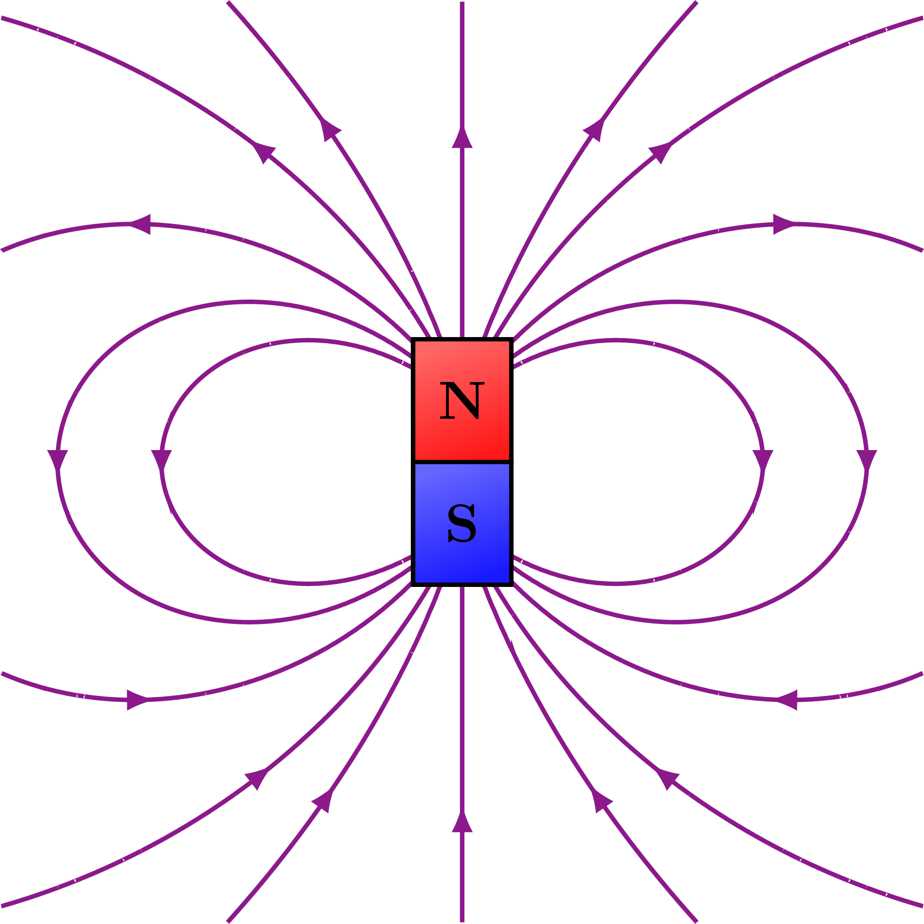
% MAGNET
\begin{tikzpicture}
\message{Magnet start. ^^J}
\def\xmin{-3}
\def\xmax{3}
\def\ymax{3}
\def\a{0.4}
\def\Q{1.0}
\def\R{1.9}
\def\range{0.05,0.1,0.2,0.3,0.4}
%\def\range{0.08,0.16,0.24,0.30,0.36}
\EFieldLines
\draw[thick,EFielLineArrow={0.65,180}] (0,-0.8) -- (0,-\ymax);
\draw[thick,EFielLineArrow={0.65,0}] (0,0.8) -- (0,\ymax);
\pic[rotate=0] (L) at (0,0) {magnet};
%\pic[rotate=-55] at (125:\E) {minimagnet};
\message{Magnet done. ^^J}
\end{tikzpicture}
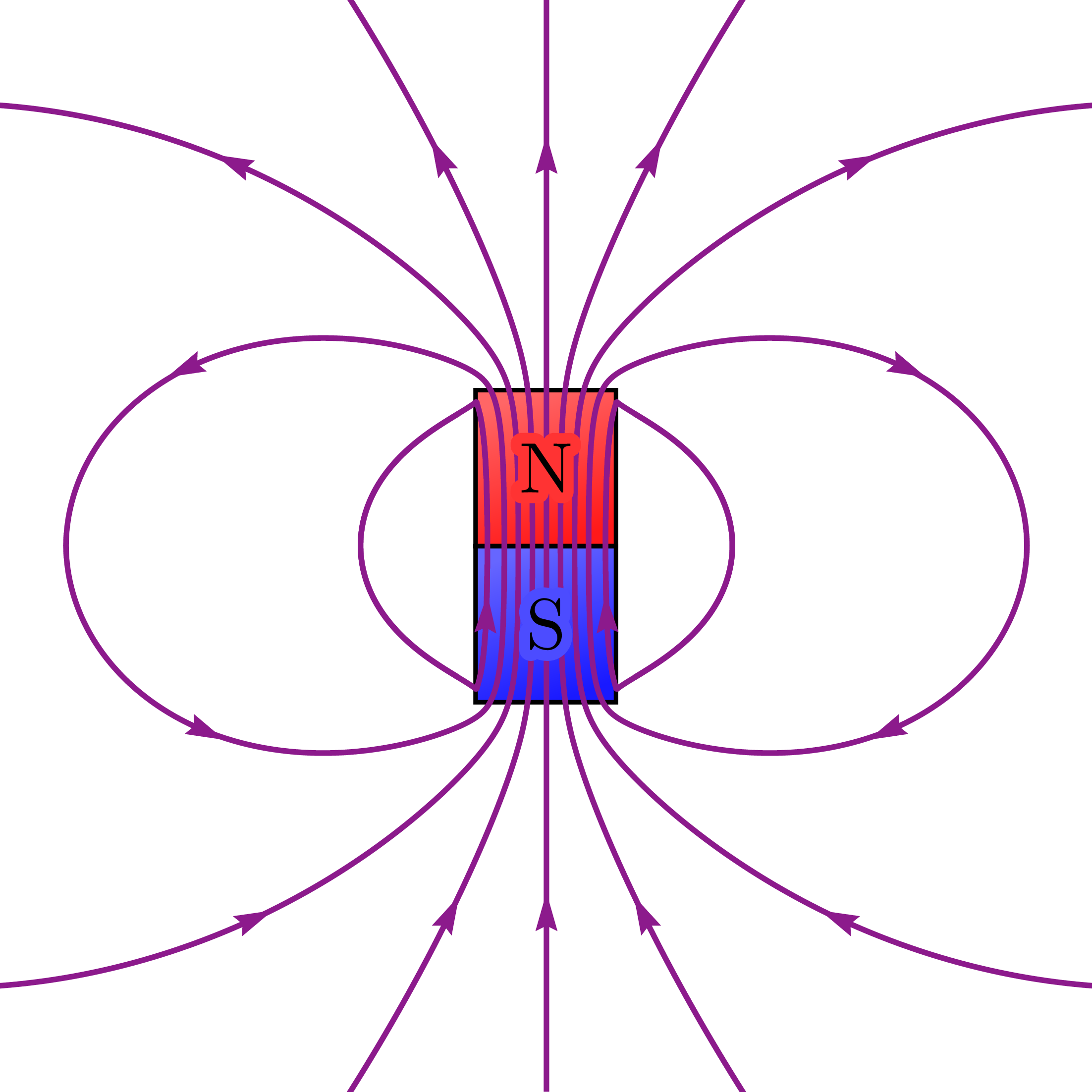
% MAGNET with PSTricks
\def\xmax{3.5}
\def\ymax{3.5}
\begin{tikzpicture}[shift={(\xmax+0.024,\ymax+0.024)}]
\message{Magnet (PSTricks) start. ^^J}
\def\H{1}
\def\W{0.45}
\draw[north] (-\W,0) rectangle (\W, \H);
\draw[south] (-\W,0) rectangle (\W,-\H);
\begin{scope} %[shift={(3,3)}]
\clip (-\xmax,-\ymax) rectangle (\xmax,\ymax); %[shift={(0,-10)}]
%\psset{unit=0.5}
\psset{arrowinset=0} % does not work?
%\newpsstyle{sensCourant}{arrowinset=0}
\begin{pspicture*}(-\xmax,-\ymax)(\xmax,\ymax) %[shift=-10]
\psframe[linecolor=white](-\xmax,-\ymax)(\xmax,\ymax)
%\psframe[linecolor=black, fillstyle=solid,fillcolor=Ncol](-1,0)(1,3)
%\psframe[linecolor=black, fillstyle=solid,fillcolor=Scol](-1,0)(1,-3)
\psmagneticfield[
N=120,R=\W,L=2, %-0.005,
nL=4,pointsB=800,
nS=1,numSpires=10,pointsS=1500,
linewidth=1.0pt,linecolor=Bcol,drawSelf=false
](-\xmax,-\ymax)(\xmax,\ymax)
%\rput(0,-5.2){\textcolor{white}{S}}
%\rput(0,5.2){\textcolor{white}{N}}
\end{pspicture*}
\end{scope}
\node[scale=1.3] at (0, \H/2) {\contour{red!80}{N}};
\node[scale=1.3] at (0,-\H/2) {\contour{blue!70}{S}};
\message{Magnet (PSTricks) done. ^^J}
\end{tikzpicture}
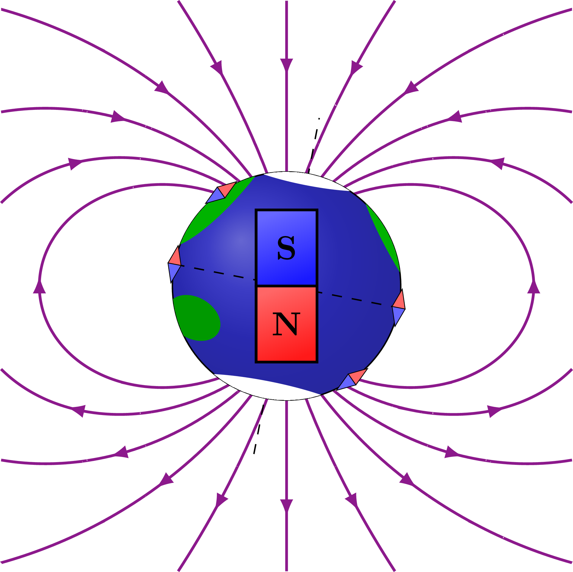
% EARTH
\begin{tikzpicture}
\message{Earth start. ^^J}
\def\xmin{-3}
\def\xmax{3}
\def\ymax{3}
\def\a{0.60}
\def\Q{-1.0}
\def\R{1.76}
\def\E{1.2}
%\def\range{0.005,0.02,0.05,0.10}
\def\range{-0.05,-0.15,-0.25,-0.35,-0.45}
\EFieldLines
\draw[thick,EFielLineArrow={0.74,0}] (0,-0.8) -- (0,-\ymax);
\draw[thick,EFielLineArrow={0.64,180}] (0,0.8) -- (0,\ymax);
\draw[dashed,rotate=-11] (0,-1.5*\E) -- (0,1.5*\E);
\fill[blue!70!black!80] (0,0) circle (1.2);
\draw[ball color=blue!70!black!90,fill opacity=0.3] (0,0) circle (\E);
\begin{scope}[rotate=-11]
\clip (0,0) circle (\E);
\fill[white] (0,\E) ellipse ({0.6*\E} and {0.10*\E});
\fill[white] (0,-\E) ellipse ({0.8*\E} and {0.15*\E});
\fill[green!70!black,rotate=-30] (160:1.1*\E) ellipse ({0.2*\E} and {0.8*\E});
\fill[green!70!black,rotate=40] (-10:1.14*\E) ellipse ({0.2*\E} and {0.9*\E});
%\fill[brown!70!black!60,draw=green!60!black,very thick,rotate=-20]
% (230:0.86*\E) ellipse ({0.25*\E} and {0.2*\E});
\fill[green!60!black,very thick,rotate=-20] % Australia
(230:0.86*\E) ellipse ({0.25*\E} and {0.18*\E});
\draw[dashed] (-\E,0) -- (\E,0);
\end{scope}
\pic[rotate=180,scale=1.0] at (0,0) {magnet};
%\pic[rotate=0] at (0,0) {minimagnet};
%\pic[rotate=0] at (-\E,0) {minimagnet};
%\pic[rotate=0] at (\E,0) {minimagnet};
\pic[rotate=-55] at (125:\E) {minimagnet};
\pic[rotate=-55] at (-55:\E) {minimagnet};
\pic[rotate=-11] at (180-11:\E) {minimagnet};
\pic[rotate=-11] at (-11:\E) {minimagnet};
\message{Earth done. ^^J}
\end{tikzpicture}
\end{document}
Click to download: magnet_fieldlines_dipoles.tex • magnet_fieldlines_dipoles.pdf
Open in Overleaf: magnet_fieldlines_dipoles.tex
")


Hi Issak, Thanks for this wonderfull and great job!
I’am wondering why this code wouldn;t compile on my computer and shows me this error below:
Package pgf Error: No shape named `intersection-1′ is known. \EFieldLines
Package pgf Error: No shape named `intersection-0′ is known. \EFieldLines
Hey Sofiane,
Sorry for the late reply, I only saw your comment now!
Did you perhaps run the code after changing some of the contour ranges in \range or the figure size? To place arrowheads on the field lines, the \EFieldLines macro computes intersections with an ellipse or straight line. From the error you shared it looks like no intersections were found (\Nb=0), so the foreach “\foreach \i in {1,…,\Nb}” tries to loop from 1 to 0, but “intersection-1” and “intersection-0” do not exist. This might require some finetuning of the contours or ellipse, or you could just disable this part in \EFieldLines.
Cheers,
Izaak