")


The pseudo force (or fictitious force) due to the acceleration of a non-inertial frame of reference S'.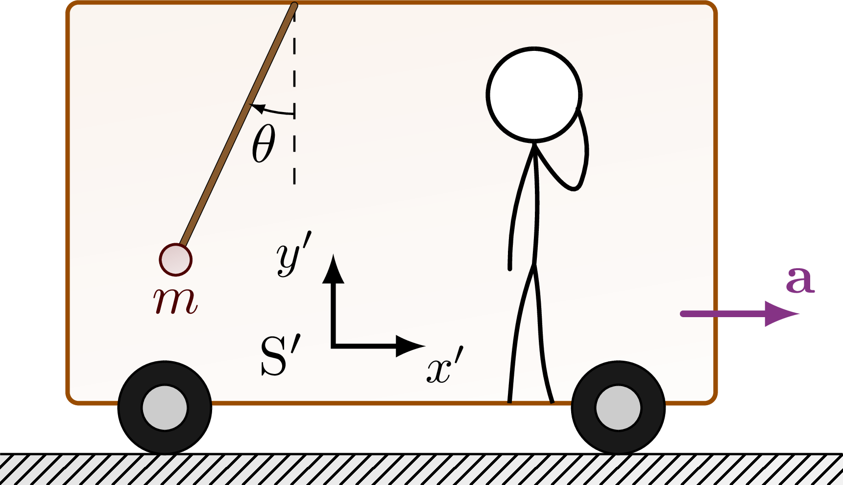 Force diagram of the mass in inertial 'lab' frame S:
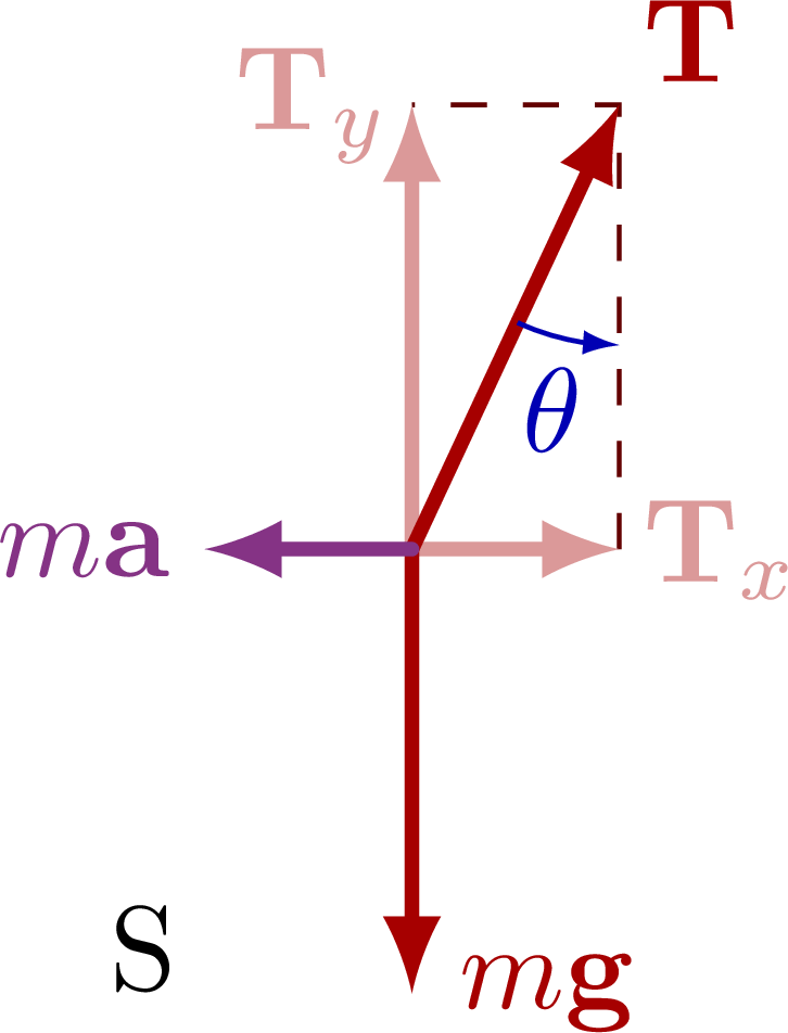 Force diagram in the non-inertial frame S' with the pseudo force F'.
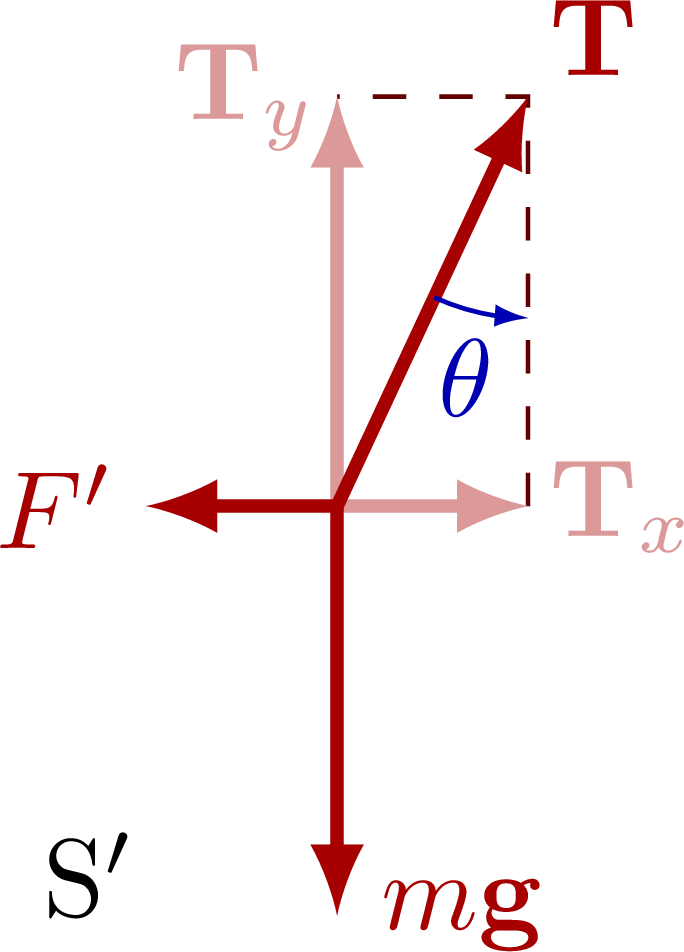
Edit and compile if you like:
% Author: Izaak Neutelings (September 2020)
\documentclass[border=3pt,tikz]{standalone}
\usepackage{amsmath}
\usepackage{tikz}
\usepackage{physics}
\usetikzlibrary{calc}
\usetikzlibrary{angles,quotes} % for pic
\usetikzlibrary{arrows.meta} % for arrow size
\usetikzlibrary{bending} % for arrow head angle
\usetikzlibrary{patterns}
\tikzset{>=latex} % for LaTeX arrow head
\usepackage{xcolor}

\colorlet{xcol}{blue!70!black}
\colorlet{vcol}{green!45!black}
\colorlet{acol}{red!50!blue!80!black!80}
\tikzstyle{vvec}=[->,very thick,vcol,line cap=round]
\tikzstyle{avec}=[->,very thick,acol,line cap=round]
\colorlet{myred}{red!65!black}
\tikzstyle{force}=[->,myred,very thick,line cap=round]
\tikzstyle{Fproj}=[force,myred!40]
\tikzstyle{ground}=[preaction={fill,top color=black!10,bottom color=black!5,shading angle=20},
                    fill,pattern=north east lines,draw=none,minimum width=0.3,minimum height=0.6]
\tikzstyle{mass}=[line width=0.5,red!30!black,fill=red!40!black!10,rounded corners=1,
                  top color=red!40!black!20,bottom color=red!40!black!10,shading angle=20]
\tikzstyle{rope}=[brown!70!black,line width=1,line cap=round] %very thick
\tikzstyle{myarr}=[-{Latex[length=3,width=2]},thin]
\def\rope#1{ \draw[rope,black,line width=1.4] #1; \draw[rope,line width=1.1] #1; }
\def\car{
  \draw[thick,rounded corners=2,orange!60!black,
        top color=orange!70!black!6,bottom color=orange!70!black!2,shading angle=10]
    (0,1.1*\CR) rectangle++ (\CW,\CH);
  \fill[black!20]
    (0.15*\CW,\CR) circle(\CR) (0.85*\CW,\CR) circle(\CR);
  \draw[black,fill=black!90,thin,even odd rule]
    (0.15*\CW,\CR) circle(\CR) circle(0.5*\CR)
    (0.85*\CW,\CR) circle(\CR) circle(0.5*\CR);
}

\begin{document}


% MOVING REFERENCE FRAME
\def\ang{-115}   % rope angle
\begin{tikzpicture}
  \def\r{0.10}    % mass radius
  \def\H{2.0}     % human height
  \def\CW{4.2}    % car width
  \def\CH{2.6}    % car height
  \def\CR{0.3}    % wheel radius
  \def\W{1.30*\CW} % ground width
  \def\D{0.2}      % ground depth
  \def\L{0.7*\CH}  % rope length
  \coordinate (T) at (0.35*\CW,\CH+\CR+0.01);

  % SETUP
  \draw[ground] (-0.08*\W,0) rectangle++ (\W,-\D);
  \draw (-0.08*\W,0) --++ (\W,0);

  % CAR 1
  \car
  \draw[thick,fill=white] (0.72*\CW,\H+\CR+0.03) circle (0.15*\H) coordinate (H);
  \draw[thick] (H)++(-90:0.15*\H) coordinate (N) to[out=-85,in=85]++ (0,-0.40*\H) coordinate (P);
  \draw[thick,line cap=round] (N)++(-85:0.03) to[out=-110,in=90]++ (-0.08*\H,-0.4*\H);
  \draw[thick,line cap=round] (N)++(-85:0.03) to[out=-60,in=-110]++ (0.15*\H,-0.12*\H)  to[out=70,in=-70]++ (-0.01*\H,0.24*\H);
  \draw[thick] (P) to[out=-110,in=85] ($(H)+(-0.08*\H,-\H)$);
  \draw[thick] (P) to[out=-80,in=108] ($(H)+(0.06*\H,-\H)$);
  \draw[avec] (0.95*\CW,0.35*\CH) --++ (0.18*\CW,0) node[above] {$\vb{a}$};

  % MASS
  \draw[dashed] (T) --++ (0,-0.65*\L) coordinate (B);
  \rope {(T) --++ (\ang:\L) coordinate (M)};
  \draw pic[{Latex[length=3,width=2,flex'=1]}-,"$\theta$",draw,angle radius=20,angle eccentricity=1.3] {angle=M--T--B};
  \draw[mass] (M) circle(\r) node[below=2] {$m$};

  % AXIS
  \node (A) at (0.33*\CW,0.25*\CH) {S$'$};
    \draw[<->,line width=0.9]
      (A)++(0.08*\CW,0.25*\CH) node[left,scale=0.9] {$y'$} |-++
           (0.3*\H,-0.30*\H) node[below right=-3.5,scale=0.9] {$x'$};

\end{tikzpicture}


% PENDULUM FORCES
\begin{tikzpicture}
  \def\FG{1.3}  % weight force (mg) magnitude
  \coordinate (O) at (0,0);
  \coordinate (FT) at (180+\ang:{\FG/cos(90+\ang)});
  \coordinate (FTx) at ({\FG*tan(90-\ang)},0);
  \coordinate (FTy) at (0,\FG);
  \coordinate (FG) at (-90:\FG);
  \coordinate (FGx) at (-90+\ang:{0.7*\FG});
  \coordinate (MA) at ({\FG*tan(\ang-90)},0);
  \draw[dashed,myred!60!black] (FTx) -- (FT) -- (FTy);
  \draw[Fproj] (O) -- (FTy) node[left=-2] {$\vb{T}_y$};
  \draw[Fproj] (O) -- (FTx) node[right=-2] {$\vb{T}_x$};
  \draw[force] (O) -- (FT) node[above right=-2] {$\vb{T}$};
  \draw[force] (O) -- (FG) node[right=0] {$m\vb{g}$};
  \draw[avec] (O) -- (MA) node[left=-1] {$m\vb{a}$};
  \draw pic[myarr,"$\theta$",xcol,draw=xcol,angle radius=20,angle eccentricity=1.3] {angle=O--FT--FTx};
  \node at ({1.3*\FG*tan(\ang-90)},-0.9*\FG) {S};
\end{tikzpicture}


% PENDULUM FORCES
\begin{tikzpicture}
  \def\FG{1.3}  % weight force (mg) magnitude
  \coordinate (O) at (0,0);
  \coordinate (FT) at (180+\ang:{\FG/cos(90+\ang)});
  \coordinate (FTx) at ({\FG*tan(90-\ang)},0);
  \coordinate (FTy) at (0,\FG);
  \coordinate (FG) at (-90:\FG);
  \coordinate (FGx) at (-90+\ang:{0.7*\FG});
  \coordinate (MA) at ({\FG*tan(\ang-90)},0);
  \draw[dashed,myred!60!black] (FTx) -- (FT) -- (FTy);
  \draw[Fproj] (O) -- (FTy) node[left=-2] {$\vb{T}_y$};
  \draw[Fproj] (O) -- (FTx) node[right=-2] {$\vb{T}_x$};
  \draw[force] (O) -- (FT) node[above right=-2] {$\vb{T}$};
  \draw[force] (O) -- (FG) node[right=0] {$m\vb{g}$};
  \draw[force] (O) -- (MA) node[left=-1] {$F'$};
  \draw pic[myarr,"$\theta$",xcol,draw=xcol,angle radius=20,angle eccentricity=1.3] {angle=O--FT--FTx};
  \node at ({1.3*\FG*tan(\ang-90)},-0.9*\FG) {S$'$};
\end{tikzpicture}


\end{document}
Click to download: reference_frame_noninertial.tex • reference_frame_noninertial.pdf
Open in Overleaf: reference_frame_noninertial.tex


