")


Edit and compile if you like:
% Author: Izaak Neutelings (March 2020)
\documentclass[border=3pt,tikz]{standalone}
\usepackage{amsmath} % for \dfrac
\usepackage{physics}
\usepackage{ifthen}
\usepackage{tikz,pgfplots}
\usepackage{tikz-3dplot}
\usepackage{auto-pst-pdf}
\usepackage{pst-magneticfield}
\usepackage[outline]{contour} % glow around text
\usetikzlibrary{angles,quotes} % for pic (angle labels)
\usetikzlibrary{arrows,arrows.meta}
\usetikzlibrary{calc}
\usetikzlibrary{decorations.markings}
\tikzset{>=latex} % for LaTeX arrow head
\usepackage{xcolor}
\colorlet{Ecol}{orange!90!black}
\colorlet{EcolFL}{orange!80!black}
\colorlet{veccol}{green!45!black}
\colorlet{projcol}{blue!70!black}
\colorlet{EFcol}{red!60!black}
\colorlet{Bcol}{violet!90}
\colorlet{Bcol1}{violet!80!blue!90}
\colorlet{Bcol2}{violet!80!red!90}
\colorlet{BFcol}{red!70!black}
\colorlet{veccol}{green!45!black}
\colorlet{Icol}{blue!70!black}
\colorlet{Ampcol}{green!60!black!70}
\tikzstyle{BField}=[->,thick,Bcol]
\tikzstyle{current}=[->,Icol,thick]
\tikzstyle{force}=[->,thick,BFcol]
\tikzstyle{vector}=[->,thick,veccol]
\tikzstyle{velocity}=[->,very thick,vcol]
\tikzstyle{metal}=[top color=black!15,bottom color=black!25,middle color=black!20,shading angle=10]
\tikzstyle{darkmetal}=[top color=black!40,bottom color=black!70,middle color=black!30,shading angle=10]
\tikzstyle{lightmetal}=[thin,black!20,top color=black!3,bottom color=black!6,middle color=black!1,shading angle=10]
\tikzstyle{proj}=[projcol!80,line width=0.08] %very thin
\tikzstyle{area}=[draw=veccol,fill=veccol!80,fill opacity=0.6]
\tikzstyle{measline}=[{Latex[length=3]}-{Latex[length=3]}]
\tikzset{
BFieldLine/.style={thick,Bcol,decoration={markings,mark=at position #1 with {\arrow{latex}}},
postaction={decorate}},
BFieldLine/.default=0.5,
Ampcurve/.style={Ampcol,decoration={markings,mark=at position #1 with {\arrow{latex}}},
postaction={decorate}},
Ampcurve/.default=0.55,
pics/Bin/.style={
code={
\def\R{0.12}
\draw[pic actions,line width=0.6,#1,fill=white] % ,thick
(0,0) circle (\R) (-135:.75*\R) -- (45:.75*\R) (-45:.75*\R) -- (135:.75*\R);
}},
pics/Bout/.style={
code={
\def\R{0.12}
\draw[pic actions,line width=0.6,#1,fill=white] (0,0) circle (\R);
\fill[pic actions,#1] (0,0) circle (0.3*\R);
}},
pics/Bin/.default=Bcol,
pics/Bout/.default=Bcol,
}
\tikzstyle{measure}=[fill=white,midway,outer sep=2]
%\newcommand\arrmark[1]{mark=at position #1 with {\arrow{latex}}}
%\def\myarrmark#1{mark=at position #1 with {\arrow{latex}}}
\contourlength{1.4pt}
% RING SHADING
\makeatletter
\pgfdeclareradialshading[tikz@ball]{ring}{\pgfpoint{0cm}{0cm}}%
{rgb(0cm)=(1,1,1);
rgb(0.719cm)=(1,1,1);
color(0.72cm)=(tikz@ball);
rgb(0.9cm)=(1,1,1)}
\tikzoption{ring color}{\pgfutil@colorlet{tikz@ball}{#1}\def\tikz@shading{ring}\tikz@addmode{\tikz@mode@shadetrue}}
\makeatother
\begin{document}
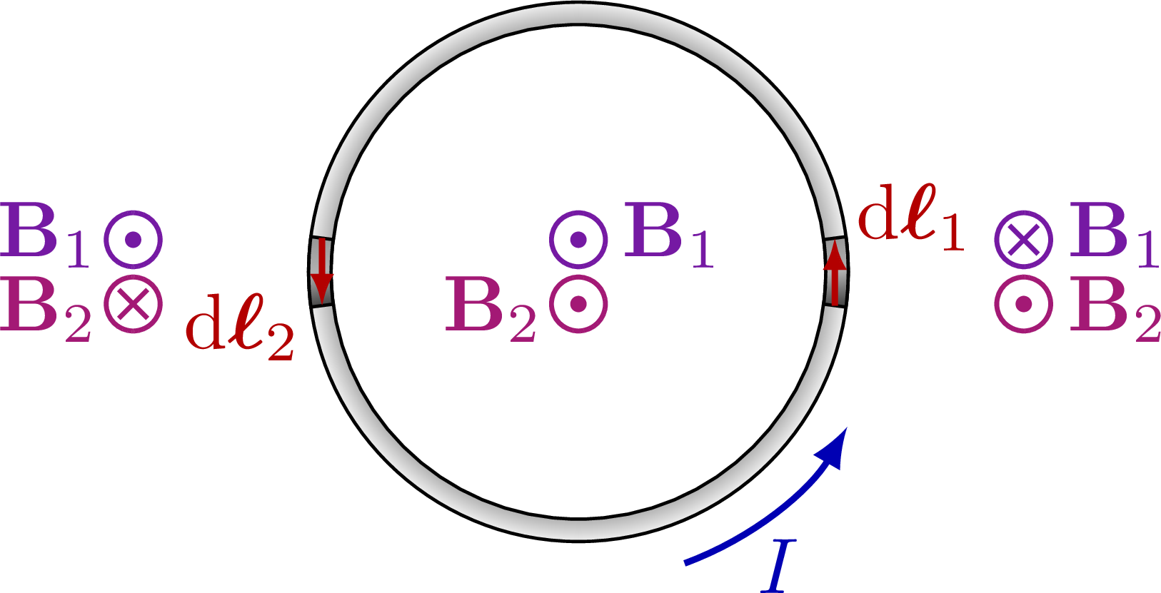
% LOOP CURRENT 2D
\begin{tikzpicture}
% VARIABLE
\def\Rin{1.1}
\def\Rout{1.2}
\def\dphi{15}
\coordinate (O) at (0,0);
\coordinate (P) at (0:\Rin);
% WIRE
\draw[shading=ring, ring color=black!60,even odd rule]
(0,0) circle (\Rin) circle (\Rout);
%\fill[metal]
% (\Rin,\Rout) -- (0,\Rout) --
% (0,\Rin) -- (\Rin,\Rin);
% DARK
\draw[darkmetal] %,even odd rule]
(-\dphi/2:\Rin) arc (-\dphi/2:\dphi/2:\Rin) -- (\dphi/2:\Rout) arc (\dphi/2:-\dphi/2:\Rout) -- cycle;
\draw[darkmetal] %,even odd rule]
(180-\dphi/2:\Rin) arc (180-\dphi/2:180+\dphi/2:\Rin) -- (180+\dphi/2:\Rout) arc (180+\dphi/2:180-\dphi/2:\Rout) -- cycle;
% VECTORS
\draw[force,-{Latex[length=4,width=3]}]
(-\dphi/2:{(\Rin+\Rout)/2}) -- (\dphi/2:{(\Rin+\Rout)/2}) node[midway,above right=-1] {$\dd\vb*{\ell}_1$};
\draw[force,-{Latex[length=4,width=3]}]
(180-\dphi/2:{(\Rin+\Rout)/2}) -- (180+\dphi/2:{(\Rin+\Rout)/2}) node[midway,below left=-1] {$\dd\vb*{\ell}_2$};
\draw[current,domain=0:40,samples=10]
(-70:1.15*\Rout) arc (-70:-30:1.15*\Rout) node[midway,below] {$I$};
% MAGNETIC FIELD
%\draw[BField] (X) -- (BY) node[right=-1] {$\dd{\vb{B}_\perp}$};
\pic at (0, 0.13*\Rin) {Bout={Bcol1}};
\pic at (0,-0.13*\Rin) {Bout={Bcol2}};
\pic at ( 1.8*\Rin, 0.13*\Rin) {Bin={Bcol1}};
\pic at ( 1.8*\Rin,-0.13*\Rin) {Bout={Bcol2}};
\pic at (-1.8*\Rin, 0.13*\Rin) {Bout={Bcol1}};
\pic at (-1.8*\Rin,-0.13*\Rin) {Bin={Bcol2}};
\node[Bcol1,right=2] at (0, 0.15*\Rin) {$\vb{B}_1$};
\node[Bcol2,left=1] at (0,-0.15*\Rin) {$\vb{B}_2$};
\node[Bcol1,right=2] at (1.8*\Rin, 0.15*\Rin) {$\vb{B}_1$};
\node[Bcol2,right=2] at (1.8*\Rin,-0.15*\Rin) {$\vb{B}_2$};
\node[Bcol1,left=1] at (-1.8*\Rin, 0.15*\Rin) {$\vb{B}_1$};
\node[Bcol2,left=1] at (-1.8*\Rin,-0.15*\Rin) {$\vb{B}_2$};
\end{tikzpicture}
% LOOP CURRENT 3D
\tdplotsetmaincoords{70}{100}
\begin{tikzpicture}[scale=3,tdplot_main_coords]
% VARIABLE
\def\t{0.01}
\def\Rin{0.7}
\def\Rout{0.74}
\def\Bpara{0.26}
\def\Bperp{0.24}
\def\rvec{1.3}
\def\thetavec{50}
\def\phivec{70}
\def\dtheta{10}
\def\dphi{15}
\coordinate (O) at (0,0,0);
\coordinate (P) at ({\Rin*cos(\phivec)},{\Rin*sin(\phivec)},{1.4*\t*cos(\phivec)});
\coordinate (P0) at (0:0.96*\Rin);
\coordinate (X) at (0,0,1.0*\Rin);
\coordinate (BY) at ({\Bpara*cos(\phivec)},{\Bpara*sin(\phivec)},1.0*\Rin);
\coordinate (BX) at (0,0,1.0*\Rin+\Bperp);
\coordinate (B) at ({\Bpara*cos(\phivec)},{\Bpara*sin(\phivec)},1.0*\Rin+\Bperp);
% WIRE
\draw[dashed] (0,0,0) -- (0,0,-0.5*\Rin);
\draw[shading=ring, ring color=black!60,domain=0:360,samples=120,even odd rule]
plot ({\Rin*cos(\x)},{\Rin*sin(\x)},{\t*cos(\x)})
plot ({\Rout*cos(\x)},{\Rout*sin(\x)},{-\t*cos(\x)});
\draw[dashed] (0,0,1.39*\Rin) -- (0,0,0);
% DARK
\draw[darkmetal,domain=0:\dphi,samples=20] %,even odd rule]
(P) --
plot ({\Rin*cos(\phivec+\x)},{\Rin*sin(\phivec+\x)},{\t*cos(\phivec+\x)}) to[out=60,in=80]
(\phivec+\dphi:\Rout) --
plot ({\Rout*cos(\phivec+\dphi-\x)},{\Rout*sin(\phivec+\dphi-\x)},{-\t*cos(\phivec+\dphi-\x)}) to[out=90,in=40]
cycle;
\draw[dashed] (O) -- (P);
\draw[dashed] (O) -- (P0);
% VECTORS
\draw[vector] (P) -- (X) node[left=3,below left=2] {$\vb{r}$};
\draw[force,-{Latex[length=4,width=3]}]
(P) --++ ({-0.3*\Rin*sin(\phivec+\dphi/2)},{0.3*\Rin*cos(\phivec+\dphi/2)},0) node[above left=-2] {$\vb*{\ell}$};
\draw[dashed,very thin] (BY) -- (B) -- (BX);
\draw[BField] (X) -- (BY) node[right=-1] {$\dd{\vb{B}_\perp}$};
\draw[BField] (X) -- (BX) node[left=-1] {$\dd{\vb{B}_\parallel}$};
\draw[BField] (X) -- (B) node[above right=-1] {$\dd{\vb{B}}$};
\draw[current,domain=0:40,samples=10]
(-40:1.15*\Rout) arc (-40:-10:1.15*\Rout) node[midway,below] {$I$};
% plot ({1.1*\Rout*cos(-20+\x)},{1.1*\Rout*sin(-20+\x)},0)
% ANGLES
%\tdplotdrawarc[->]{(O)}{0.29*\rvec}{0}{\phivec}
% {anchor=north}{$\phi$}
%\tdplotdrawarc[->]{(O)}{0.4*\rvec}{\phivec}{\phivec+\dphi}
% {above=0.5,anchor=123}{\contour{white}{$\dd{\phi}$}}
\tdplotdrawarc[->]{(O)}{0.30*\Rin}{0}{\phivec}
{below=-1,scale=1}{\contour{white}{$\phi$}}
\tdplotsetthetaplanecoords{\phivec}
\tdplotdrawarc[->,tdplot_rotated_coords]{(P)}{0.2*\Rin}{-90}{atan(1.1)-90}
{above=2,left=-1,scale=1}{$\theta$}
\tdplotdrawarc[->,tdplot_rotated_coords]{(X)}{0.2*\Rin}{0}{atan(1.1)}
{right=2,above=-1,scale=1}{\contour{white}{$\theta$}}
\end{tikzpicture}
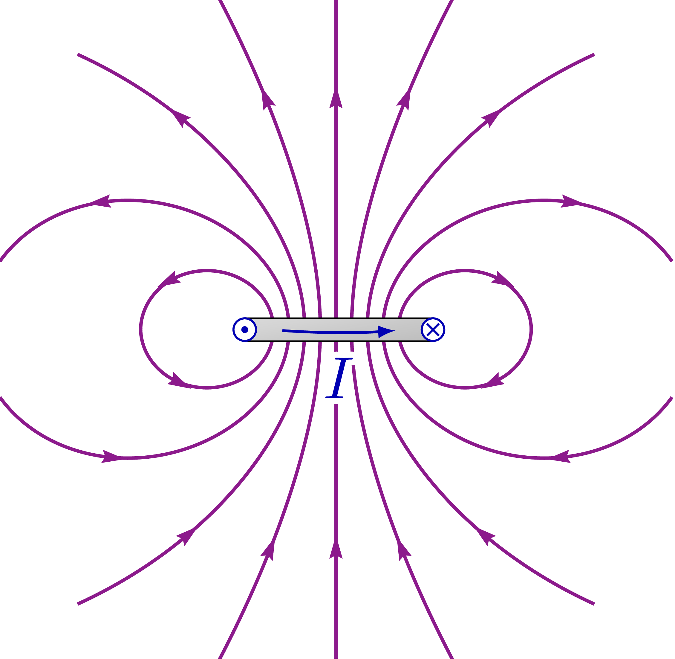
% LOOP MAGNETIC FIELD
\def\xmax{3.6}
\def\ymax{3.5}
\contourlength{1.0pt}
\begin{tikzpicture}[shift={(\xmax+0.024,\ymax+0.024)}]
\message{Loop start. ^^J}
\def\R{1}
\begin{scope} %[shift={(3,3)}]
\clip (-\xmax,-\ymax) rectangle (\xmax,\ymax);
\begin{pspicture*}(-\xmax,-\ymax)(\xmax,\ymax)
\psframe[linecolor=white](-\xmax,-\ymax)(\xmax,\ymax)
\psmagneticfield[
N=1,R=\R,L=2, %-0.005,
nL=5,pointsB=200,
nS=0,%numSpires=10,pointsS=500,
linewidth=1.0pt,linecolor=Bcol,drawSelf=false
](-\xmax,-\ymax)(\xmax,\ymax)
\end{pspicture*}
\end{scope}
\draw[metal] (-\R,0.122*\R) -| (\R,-0.122*\R) -| cycle;
\pic[scale=1] at (-\R,0) {Bout={Icol}};
\pic[scale=1] at ( \R,0) {Bin={Icol}};
\draw[current] (-0.6*\R,-0.01*\R) arc (-94:-86:{0.6*\R/sin(4)})
node[midway,below=0.8,scale=1.8] {\contour{white}{$I$}};
\message{Loop done. ^^J}
\end{tikzpicture}
\end{document}
Click to download: magnetic_field_loop.tex • magnetic_field_loop.pdf
Open in Overleaf: magnetic_field_loop.tex


Hello,
The magnetic field lines for the bottom image are not showing up when I try this on Overleaf.
The magnetic field lines are not showing. Too bad because that’s what I was looking for 🙁
The other schemes are very nice though.